Continue to Site

Welcome to EDAboard.com

Welcome to our site! EDAboard.com is an international Electronics Discussion Forum focused on EDA software, circuits, schematics, books, theory, papers, asic, pld, 8051, DSP, Network, RF, Analog Design, PCB, Service Manuals... and a whole lot more! To participate you need to register. Registration is free. Click here to register now.

How to get +5V to -5V??

Status
Not open for further replies.

shaswat

Advanced Member level 4
Full Member level 1
Joined
Jul 2, 2013
Messages
115
Helped
1
Reputation
2
Reaction score
1
Trophy points
18
Visit site
Activity points
963
I need to know that if I want a invert power supply then which type of ciruit should I use in order to get a invert supply.e.g. If I have a 5 V supply and I need to drive a circuit with -5 V then what is the circuit? How can I get this ??
 

Hi Shaswat
I would suggest to go with inverting amplifier circuit using LM741 Chipset.
 

G'day,

There are a number of ways... I've used an LT3462A https://www.linear.com/product/LT3462 converter from LT with good results... but it depends on your current requirements... it's good for 400mA or so. A buck-boost topology in standard configuration will result in an output voltage of opposite polarity to the input.
What if I don't want any IC. Actually I found TI IC which is also good and do the same as you suggest. Is there an y way to convert it using any parasitic configuration?
 

What you really need is to swap the power supply terminals. To do it you must be sure that the 5V DC power supply is isolated from ground. Any good 5VDC plug-in AC-DC converter can be used that way.

- - - Updated - - -

With any supply or battery: the polarity depends on what terminal you connect to "ground". If you connect the negative to ground, you have +5V output, and reverse.
 

Hi Shaswat
I would suggest to go with inverting amplifier circuit using LM741 Chipset.


Thanxx that would be a great answer

- - - Updated - - -

What you really need is to swap the power supply terminals. To do it you must be sure that the 5V DC power supply is isolated from ground. Any good 5VDC plug-in AC-DC converter can be used that way.

- - - Updated - - -

With any supply or battery: the polarity depends on what terminal you connect to "ground". If you connect the negative to ground, you have +5V output, and reverse.


+1 as I got something very useful from your post. But what for the non isolated power supply, someone suggest LM741, other dude tells 555 timer. Which one is good to get the desired output??

- - - Updated - - -

+1 as I get something very useful from your post. But what for the non isolated power supply, someone suggest LM741, other dude tells 555 timer. Which one is good to get the desired output??
 

Thanxx that would be a great answer

No its not a great answer. It's totally wrong. The only way you can get -5v from 741 is you are already supplying it with a -ve power rail which would have to be even more negative ... -6 -7 volts. And where do you get that from ?

Now if you ONLY require a -5v, then post#5 would be a simple answer. However we are assuming you require both +5v and -5v at the same time. Here too you can adapt #5 suggestion by using two adaptors connected in series. Just make sure the gnd is isolated.

Lastly, if you have to derive the -5v from the +5v, then you can try #6 suggestion. However you will prob not achieve -5v, but something less. And that too with low current capability.
 

What if I don't want any IC. Actually I found TI IC which is also good and do the same as you suggest. Is there an y way to convert it using any parasitic configuration?

Which IC do you have? And what do you mean by "parasitic config.." ??

If you have a converter IC for this purpose, then just look up its data sheets to see how to use it.
 

This is the converter IC that I found on internet.

https://www.ti.com/product/tps63700

There is no direct applicaiton of this IC as well as my question from my designing. I just want to learn is it possible to invert the supply using R,L,C.
 

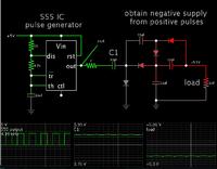
To get -5V from the 555 and voltage multiplier, you would add two more diode-capacitor cells.

Screenshot:


If you make the capacitor values larger, you will get a greater output amplitude. You can then regulate it to -5V if you wish. (This assumes the 555 can supply sufficient current. I installed a 7 ohm resistor to represent some amount of internal resistance.)

Sorry to say but its difficult for me to understand how do get that negative voltage from the postive one.
How this diodes configuration works?
 

Sorry to say but its difficult for me to understand how do get that negative voltage from the postive one.
How this diodes configuration works?

Ah yes, I too asked the same question when I saw voltage multipliers in electronics tutorials. And then there were circuits that turn positive into negative, too.

The explanations were helpful but only in a vague way.

Once I had a Macintosh computer, I got the idea of programming an animated simulator. It would be like seeing what was going on inside the wires.

This is my Youtube video which consists of an animated simulation of a simple charge-pump doubler.

https://www.youtube.com/watch?v=3czj7J_FE_k

Several voltage triplers:

https://www.youtube.com/watch?v=KXppi0_b3NY

I have also found Falstad's animated simulator to be helpful. Click the link below. It will open the website falstad.com/circuit, load my schematic (above) into his simulator, and run it on your computer.

You can see what happens during each half of the cycle.
The animation depicts the direction and intensity of current in the wires.

https://tinyurl.com/plejlaa

Yes I forget about the voltage multiplier. Thanxx a ton for helping. Really I was stuck at that question and I didn't get any solution. Thanx again for getting out me from this situatipn
 

Hey kripacharya and nitishn5
Could you please justify why cant we get -5V using 741 as an inverting amplifier. As the logic goes like Vout = -Vin*Rf/Rin.
 

Hey kripacharya and nitishn5
Could you please justify why cant we get -5V using 741 as an inverting amplifier. As the logic goes like Vout = -Vin*Rf/Rin.

Hi that voltage is taken from the negative supply of the OPAMP, we are working here to get that negative voltage only, If we have it we don need a component...............
 
Hi embedsys,

While the logic goes like Vout = -Vin*Rf/Rin, this would be valid only if you have given both positive and negative supplies to the the Op-amp. For example ±15V.

Consider this, it you give the supply pins, V+ = 15V and V- = 0V, do you think that the inverting amplifier would give a negative voltage as output? The minimum it can give is 0V.(Actually since the 741 is not a rail to rail amplifier, it would probably give a minimum of about 1V or so.)

So unless you already have a negative voltage supply in hand of less than -5V, you cannot get a -5V output from an op-amp.
But then if you already have a negative voltage supply, you could as well as rectify it to get the -5V that is needed.
 
Status
Not open for further replies.

Part and Inventory Search

Welcome to EDABoard.com

Sponsor

Back
Top