Continue to Site

Welcome to EDAboard.com

Welcome to our site! EDAboard.com is an international Electronics Discussion Forum focused on EDA software, circuits, schematics, books, theory, papers, asic, pld, 8051, DSP, Network, RF, Analog Design, PCB, Service Manuals... and a whole lot more! To participate you need to register. Registration is free. Click here to register now.

[SOLVED] How to extract the dc component from a sinusoidal signal

Status
Not open for further replies.

sudip_kuet08

Junior Member level 1
Joined
Mar 27, 2012
Messages
15
Helped
0
Reputation
0
Reaction score
0
Trophy points
1,281
Location
Bangladesh
Activity points
1,401
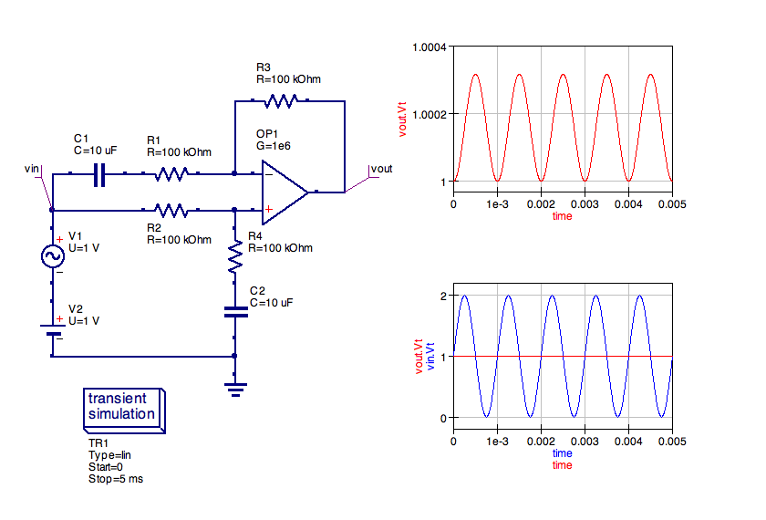
My input signal is V+Vosinwt
I want to extract the V voltage............

from the previous post I've come to know that I can do it By Low Pass filter.......but I didn't get that practically..........

please help me as soon as possible............

thanks
sudip
 

simple capacitor with suitable time constant can perform this job
but if u want use a low pass filter then use opamp integrator whiich act as low pass filter images.jpg
and then values of capacitor and resitor can be set acorrdingly
 

I think u will need a summing amp , feed the wave to - input and inverted to + input
 

i mean it should charge for the time the sine wave is rising (is above the average value)and discharge for the time when sine wave is falling(below the average value)
 

A simple RC low pass filter will extract the DC from the sinewave. You just need the RC time constant to be long enough to give an acceptable ripple voltage (whatever that is for your application) based upon the amplitude and frequency of the signal.
 

I think u will need a summing amp , feed the wave to - input and inverted to + input

Thanks for your suggestion, But as I am a student and my term final is very close I am very busy with my studies. If you please help me providing any circuit diagram....then it will be helpful to me.....

thanks in advance.
 

If you are sure the sine is pure, an alternative method is to measure the minimum and maximum voltages, the DC offset is half way between them.

Brian.
 

... please help me providing any circuit diagram...

Apart from fareen's suggestion that
simple capacitor with suitable time constant can perform this job

... which is a solution with only 2 passive components, this circuit has a considerable output resistance and load dependency -- same is valid for the true DC filter circuit.

If you're ready to spend a few more devices, I think dselec's suggestion
u will need a summing amp
... respectively a differential amp can do the job quite well, while supporting a low output impedance:

C1 & C2 block the DC voltage, as necessary. If R1*C1 = R4*C2 = RC ≈ 1000*1/fsin as chosen in the image above, the residual ripple on DC is in the promille range -- see the upper plot in the image above -- if the opAmp's CMRR (Common Mode Rejection Ratio) is good (resp. low) enough: ≦ -60dB.
 
Last edited:
Status
Not open for further replies.

Similar threads

Part and Inventory Search

Welcome to EDABoard.com

Sponsor

Back
Top