Continue to Site

Welcome to EDAboard.com

Welcome to our site! EDAboard.com is an international Electronics Discussion Forum focused on EDA software, circuits, schematics, books, theory, papers, asic, pld, 8051, DSP, Network, RF, Analog Design, PCB, Service Manuals... and a whole lot more! To participate you need to register. Registration is free. Click here to register now.

How to drive ULN2004 with 24V input

Status
Not open for further replies.

udhay_cit

Full Member level 6
Joined
May 16, 2008
Messages
346
Helped
37
Reputation
74
Reaction score
37
Trophy points
1,318
Activity points
3,895
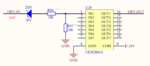
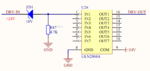
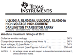
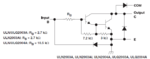
I need to drive a ULN2004 IC with 24V input. The nominal allowable driving input voltage of the IC is 5V so I need to add a voltage reducer to the input. Please give your feedback about which one of the following circuit is most recommended...!

Thanks & Regards
Udhay
 

Attachments

  • RESISTOR.PNG
    RESISTOR.PNG
    31.9 KB · Views: 1,118
  • ZENER resistor.PNG
    ZENER resistor.PNG
    31.6 KB · Views: 410
  • ZENER.PNG
    ZENER.PNG
    32.4 KB · Views: 326

hi,
The ULN2004A can accept 6V thru 15V on its input pins, so I would use two 10K's [ right side diagram]

E
 

Attachments

  • AAesp01.gif
    AAesp01.gif
    42.8 KB · Views: 227

Why don't you look at the datasheet for the ULN2004A to see that its maximum allowed input voltage is 30V?
 

Attachments

  • ULN2004A.png
    ULN2004A.png
    24.1 KB · Views: 244

Use 10K resistor in series for each input. No need for resistor to ground and don't use zeners.
 

The datasheet shows that the ULN2004A already has a 10.5k resistor in series with its input providing a maximum allowed input of 30V.
Hi Audioguru,
The absolute max is 30V. Look at the ULN2001 it doesn't have base resistor, can it take 30V ? The input rated voltage is 6-15V, this is from the datasheet too.
You and I can drive the input with 24V because we played it safe all our lives and now we say bucket! Udhay wants to do it right.
 

Hi Audioguru,
The absolute max is 30V. Look at the ULN2001 it doesn't have base resistor, can it take 30V ?
We are not talking about the ULN2001, we are talking about the ULN2004A. Texas Instruments does not make the old ULN2001 anymore. The datasheet from ST Micro lists the ULN2001 max input current, not its max input voltage because it needs an external series input current-limiting resistor.
 

Dear all,
I have experience with ULN2004 with 24V supply & 24V input & its working fine. But I'm not sure whether its a right way or not. If you look at the datasheet, the input allowable range varies with respect to collector current. Hardly my collector current will not go above 100mA & as per the datasheet electrical characteristics the maximum allowable input voltage for collector current of 125mA is 5V. Even though its working for 24V input voltage, I'm afraid to go with this design for long run.
The different between ULN2003 & ULN2004 id the base resistor. So the base resistor value is directly proportional to the given input voltage. That is the reason , I want to know what value exactly I need to add at the input for given 24V input?

Regards
Udhay
 

Attachments

  • Internal.PNG
    Internal.PNG
    21.6 KB · Views: 183
  • Voltage spec.PNG
    Voltage spec.PNG
    17.2 KB · Views: 176

Dear all,
I have experience with ULN2004 with 24V supply & 24V input & its working fine. But I'm not sure whether its a right way or not. If you look at the datasheet, the input allowable range varies with respect to collector current. Hardly my collector current will not go above 100mA & as per the datasheet electrical characteristics the maximum allowable input voltage for collector current of 125mA is 5V. Even though its working for 24V input voltage, I'm afraid to go with this design for long run.
The different between ULN2003 & ULN2004 id the base resistor. So the base resistor value is directly proportional to the given input voltage. That is the reason , I want to know what value exactly I need to add at the input for given 24V input?

Regards
Udhay

You are not reading the data properly. It is not "maximum allowable input voltage for collector current of 125mA is 5V" , it is that for 125mA the worst case input is 5V . That means that if you go below 5V and collector current 125mA the collector voltage will be more than 2V because the transistor starved of base current. You must have input voltage over 5V for 125mA collector current.
The data is confusing and that is why you got it the other way around.
Thanks for your explanation. Yes now I can remember old age transistor operation. :laugh: . But still my question is need to be answered. Is it OK to give 24V input directly to ULN2004 for driving or need any additional resistors required? :lol:
 

I've already answered this, see post #4

BTW you have to raise your voice by 40db when you answer Audioguru. :)
 
Last edited:

The maximum allowed input voltage for the ULN2004A is 30V.
The "On state Input Voltage" is the minimum input voltage you must give it for it to produce the output current shown at the saturation voltage shown (2V).
I think the datasheets wrongly say "maximum" instead of "minimum" input voltage needed.

Any darlington transistor needs more input current for it to produce more output current. In order to have more input current then the input voltage obviously must be higher as is shown.
When you provide it with a higher "On state Input Voltage" than the "minimum" listed amount then its saturation voltage will be lower then its heating will be much less and it will probably last longer.
For an output current of 125mA the "minimum" input must be only 5V so you can add a 10.5k resistor in series with its input to reduce the input to it to only 12V with your 24V signal, and it will still work very well.
 
Status
Not open for further replies.

Part and Inventory Search

Welcome to EDABoard.com

Sponsor

Back
Top