Continue to Site

Welcome to EDAboard.com

Welcome to our site! EDAboard.com is an international Electronics Discussion Forum focused on EDA software, circuits, schematics, books, theory, papers, asic, pld, 8051, DSP, Network, RF, Analog Design, PCB, Service Manuals... and a whole lot more! To participate you need to register. Registration is free. Click here to register now.

How to drive finder relay with 2N3904

Status
Not open for further replies.

jmx66

Member level 5
Joined
Nov 16, 2010
Messages
93
Helped
0
Reputation
0
Reaction score
1
Trophy points
1,288
Location
France
Activity points
2,045
Hi all,

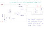
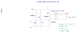
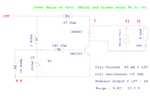
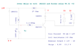
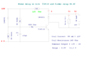
I d'be glad to get advice on this schematic , about driving a finder relay with a NPN 2N3904.

R1 and C1 are only for a delayed power on.


It'a a plug-in module, in case of failure, remove clip and put an other one, no need to desolder like a SSR.....

As usual, queries, if someone could reply, would be really great.

Are values for these resistors correct:
R3 Collector resistor
Rb Base resistor
Rl Led Resistor

I thought to add test points , but finally a green Led will do the job.

- 2N3904 Ic Maxi is about 200mA : Right use for this project, is it a power transistor or must be changed?

-About Led : Iled choice: 10mA for Vf:2,1 V


-I = 90 mA for the coil + 10 mA for the led = 100 mA

-Ic=100 mA with hfe=30 ( mini ) Vcesat=0,3V Ib=3,3mA

-Rc value (15-12-0,3)/ 100 mA= 27 Ohm Rc=27 Ohm

-Rb value for Vbe sat= 0,7 V Rb=( 15-0,7) 3,3mA Rb=4,3KOhm

-R led (12-2,1) / 10 mA R led=1MOhm

Are these basic math correct?

I made a mistake on the schematic, it is not Nominal Output , but must read Power Coil!!!!!!
Thanks a lot.

jm
 

Attachments

  • Alim-Delay-with-2N3904+finder-relay.png
    Alim-Delay-with-2N3904+finder-relay.png
    50.7 KB · Views: 167

The potential divider R1/R2 will bring the voltage down to near 10v (not taken into acount the load Rb). Your Ib current will be much less you are calculating (about 1mA). At the junction of R1 and Rb you have a voltage of about 10,7V and an impedance of 10K//20K = 6k6 (consider Rb not connected) driving Rb. The base current will be Ib=(10,7 - Vbe) / (6k6+Rb). Rled should be 1K, not 1M. The remaining calculations seem to be basicaly correct.
 

The potential divider R1/R2 will bring the voltage down to near 10v (not taken into acount the load Rb). Your Ib current will be much less you are calculating (about 1mA). At the junction of R1 and Rb you have a voltage of about 10,7V and an impedance of 10K//20K = 6k6 (consider Rb not connected) driving Rb. The base current will be Ib=(10,7 - Vbe) / (6k6+Rb). Rled should be 1K, not 1M. The remaining calculations seem to be basicaly correct.

Thanks a lot for your reply.

Best regards.

jm
 

Why is R3 there? It doesn't make sense.

What is R2 and the diode for? Again, I don't see the point. If it is to discharge the base capacitor when the power is removed then a diode to the positive rail should be used.

As pointed out earlier, your base current will be a lot lower than you think. I would remove R2, Rb and the diode and size R1 for the base current. Then increase the capacitor to suit.

Overall it is not a great circuit. The turn on will be slow and 'soft'. I would prefer something with a positive switchover.

Keith
 
  • Like
Reactions: jmx66

    jmx66

    Points: 2
    Helpful Answer Positive Rating
.Hi,

Why is R3 there? It doesn't make sense.

I need to lower voltage for relay coil 9,3 13,1 V


I have changed the circuit above, and replaced 2N3904 by 2N2222.

With advices from experienced members of this forum,I redraw my draft, this is a result, don't know , if it is really correct....

for Ib=15 mA Ic= 150 mA Vbe sat Maxi 1,3 V


Schematic-V1

Changes: R1 to 1 KOhm and R2 to 10 KOhm

C1 1500 µF

Req : 1Kohm // 10 Kohm about 1 KOhm

Maths for Rb: Ve = 15 x ( 10 / 11 ) Ve= 13,7 Volts

Choice for Ib: 10 mA 13,7 -1,3 = ( Req +Rb ) x 10 mA

Rb = 240 Ohm


Schematic-V2

Diode to discharge C1 added .

Removed 20 KOhm resistor

Added C1 1500 µF

Now for Rb 15 -1,3 = ( Rb x 10 mA) Rb= 1,4 KOhm


In fact, i need a power on delay of about 1 second.

I agree, it is not a great circuit, and that's why i need advices!!!!

Best regards.


jm**broken link removed**
 

Attachments

  • 2N2222-Low-Power-Bipolar-Transistors.pdf
    139.7 KB · Views: 89
  • Alim-Delay-with-2N2222+finder-relay-V1.png
    Alim-Delay-with-2N2222+finder-relay-V1.png
    48.7 KB · Views: 123
  • Alim-Delay-with-2N2222+finder-relay-V2.png
    Alim-Delay-with-2N2222+finder-relay-V2.png
    48.1 KB · Views: 118
Last edited:

Why not just use a 12V regulator up front and a 555 monostable for the delay and go from there?
 
Last edited:
  • Like
Reactions: jmx66

    jmx66

    Points: 2
    Helpful Answer Positive Rating
Hi,

Thanks for your reply.

In fact, i thought to add a 7812 after a 7815, but discard this solution; not enough place .

I wanted something simpler than above.

And for the 555 , with Kicad - I'm not very experienced with this soft - it seemed too difficult to route thin routes between pins.

Best regards.

jm
 

It's reasonable to target to a minimum part count and size circuit, thus I think the design is basically good. I would however prefer a MOSFET or darlington transistor to get rid of the unconvenient large capacitor. If you don't have it at hand, a darlington circuit of two individual transistors would work as well.
 
  • Like
Reactions: jmx66

    jmx66

    Points: 2
    Helpful Answer Positive Rating
Hi all,

After searching in datasheet of Darlington - FvM's advice -, found TIP110 and draw another schematic.

Added also a diode, after Keith's advice.

Data for TIP110

Maximum ratings Base current 50 mA


On characteristics

Vce sat = 2,5 Maxi Base-Emitter On Voltage 2,8 Maxi

hfe: 500 to 1000 minimum


Queries:

Is R3 Value correct? ( 15 -2,5 ) / 10 mA \approx R3 = 125 Ohm

Idem for Rb Ve = 10 V

Rb * 10mA = 10 - 2,8

Rb = 600 Ohm


I know the draft is not a high level circuit, but the question is :

Should it work ?

I know also that darlington symbol is different from a transistor.....

Thanks a lot.

jm
 

Attachments

  • Alim-Delay-with-TIP110.png
    Alim-Delay-with-TIP110.png
    55 KB · Views: 115
  • Multicomp-TIP110-TIP115-Darlington-Transistors-.pdf
    213.3 KB · Views: 87

Rb isn't needed at all, I think. R1 and R2 can be higher resistance with a darlington, and C1 possibly smaller. R3 has to be choosen such, that at least the minimal engage voltage for the relay is achieved, better, you target nearer to the nominal voltage to have some margin. Also the LED current, that hasn't been specified, must be considered. The previous value of 27 ohm results in an almost exact relay voltage of 12 V. With a darlington, the transistor saturation voltage is considerably higher, so 27 ohm isn't bad.
 
  • Like
Reactions: jmx66

    jmx66

    Points: 2
    Helpful Answer Positive Rating
Hi all,

Thanks for your replies, first.

Made changes to previous schematic: mostly removed Rb and resistors values modified.


Maths for R3:

V coil = 9,3 V ( 15 - 9,3 - 2,5 )/ 100 mA R3≈ 30 Ohm

V coil = 12 V ( 15 - 12 - 2,5 ) / 100 mA R3 ≈ 5 Ohm

Choice : 5 Ohm

About led :

I led = 10 mA
Vf = 2,1 V (12 - 2,1 ) / 100mA R led ≈ 100 Ohm


Now for R1 and R2

R1 = 10 KOhm

R2 = 20 KOhm

Req = 300 / 40 Req = 7,5 KOhm

Ve = ( 15 x 30 ) / 40 Ve = 11,25 V Ib= 1,16 mA


For R1= 10 KOhm

R2= 43 KOhm

Req= 8,11 KOhm Ve = 12,16V Ib= 1,2mA


I only want to know if Ib is sufficient enough to drive 100 mA on the coil?

Best regards.

jm
 

Attachments

  • Delay-Power-On-With-TIP-110.png
    Delay-Power-On-With-TIP-110.png
    11.2 KB · Views: 134

Status
Not open for further replies.

Part and Inventory Search

Welcome to EDABoard.com

Sponsor

Back
Top