Continue to Site

Welcome to EDAboard.com

Welcome to our site! EDAboard.com is an international Electronics Discussion Forum focused on EDA software, circuits, schematics, books, theory, papers, asic, pld, 8051, DSP, Network, RF, Analog Design, PCB, Service Manuals... and a whole lot more! To participate you need to register. Registration is free. Click here to register now.

How to drive a series LC resonance circuit?

Status
Not open for further replies.

se7ensong

Junior Member level 1
Joined
Feb 20, 2010
Messages
16
Helped
3
Reputation
6
Reaction score
3
Trophy points
1,283
Location
London
Activity points
1,388
Hello there,

I am designing an near field inductive link at 900 MHz. For some reason, I need to 1W at transmitting coil which is a serier LC circuit. I am trying to drive it with a 900MHz 30dBm Power Amplifier.

My question is, do I need to match the impedances of the PA and the LC in resonance?

If so, how should I do it? I have read something about the matching of loop antenna, but they are all parallel LC circuit.

If not, why?

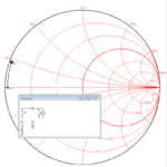
Below are the smith chart and its schematic. TP2 is point at resonance, TP1 is the coil it self tested using a PNA at 900 MHz.

https://obrazki.elektroda.pl/78_1328287668.png

Thank you in advance!
 

Attachments

  • Capture.PNG
    Capture.PNG
    41.8 KB · Views: 125

Dear se7ensong
Hello
Yes . the impedance matching is very important . and for PA , is current important to you ? if yes , you can use a gali-5 as a voltage amp , and then you can use a simple class E amp .
Good luck
Goldsmith
 

Unmatched load gives reflections back to PA.
A unmatched antenna is often ineffective from radiation view.
If that is a problem, improve matching.

A parallel tuned loop antenna can be a good alternative for near field communication. In case of near field coupling to another antenna, is tuning a simple way to increase efficiency.
A serial tuned loop antenna have the disadvantage that it is complicated to build and in most cases have more losses when matched against a 50 Ohm PA.
Two dipoles are easier then loop antennas to construct and near field coupling can be equally good.
If efficiency not is important can any antenna be selected and no need to care about impedance matching either, as long as your PA and other electronics survives the reflecting RF current.
 

Dear All
Yes , i'm completely agree with Mr kafeman. the unmatched loads can destroy the transmitter ( PA ) with bad reflections .i have seen some explosion on my first transmitters due to this effect some years ago.
Good luck
Goldsmith
 

Dear se7ensong
Hello
Yes . the impedance matching is very important . and for PA , is current important to you ? if yes , you can use a gali-5 as a voltage amp , and then you can use a simple class E amp .
Good luck
Goldsmith

Dear goldsmith,

Thank you so much for your reply. I understand the matching is very important when connecting to an antenna. But since I am connecting to a serial LC circuit, I am not sure how to do the matching now as when in resonance, what left is only the resistance of the inductor which is very small. Perhaps you can give me some hint based on the smith chart provided?

Or should I do the matching for the inductor only (DP1 in the smith chart) other than for the LC in resonance (TP2 in the smith chart)?

---------- Post added at 12:07 ---------- Previous post was at 11:57 ----------

Unmatched load gives reflections back to PA.
A unmatched antenna is often ineffective from radiation view.
If that is a problem, improve matching.

A parallel tuned loop antenna can be a good alternative for near field communication. In case of near field coupling to another antenna, is tuning a simple way to increase efficiency.
A serial tuned loop antenna have the disadvantage that it is complicated to build and in most cases have more losses when matched against a 50 Ohm PA.
Two dipoles are easier then loop antennas to construct and near field coupling can be equally good.
If efficiency not is important can any antenna be selected and no need to care about impedance matching either, as long as your PA and other electronics survives the reflecting RF current.

Dear E Kafeman,

Thank you so much for your suggestions on serial tuned loop antenna. Yes, I found it's complicated. Actually, I have some experience on driving it:

1. I did run a simulation in Cadence IC. The serial LC was driven with a voltage source with an amplitude of 1.5V. But I don't think that will work in practice because of the matching issue.

2. I have tested to drive the serial LC using a ring oscillator with a crystal at 13.56 MHz. So the chain of inverters works as a PA. But at 900 MHz, I don't think I can do that since the high frequency.

For both of the two cases, no matching network is used. That's why I get the question in the first place.

So, since the matching is so important, could you please give me an example or hints based on the smith chart I provide? Should I do the matching from DP1 or TP2?

Thank you so much
 

Dear se7ensong
Again Hi
Do you know about STUB systems ?you can design an stub for impedance matching between your networks and antenna simply . at this frequency ( 900MHZ) the stub will be better choice and easy to design .
and about smith charts , See below links , please:
http://courses.engr.illinois.edu/ece329/impedance_matching.pdf
http://etidweb.tamu.edu/ftp/entc489rf/Spring 05 Labs/ENTC 489RF Lab 5.pdf
http://cc.ee.ntu.edu.tw/~thc/course_mckt/note/note4.pdf
http://www.ece.msstate.edu/~donohoe/ece4333notes5.pdf
**broken link removed**
http://www.amanogawa.com/archive/docs/J-tutorial.pdf
Good luck
Goldsmith
 

Thank you so much. That's a lot information. I will read them first.
 

THese were all good theoretical answers. Unfortunately, in a practical sense, you are not going to easily match a 1 ohm resistive part to a 50 ohm amplifier. Why not drive the antenna with a current source instead of a 50 ohm amplifier. Or at least an amp with a very low output impedance, such as a power bipolar transistor at the output.

Also, with such a small resistive part, make sure the antenna is made with wide copper traces to keep the copper losses down compared to the radiation resistance. Otherwise most of your transmit power will be turned to heat.
 
Last edited:
Dear biff44
Hi
The power transistors has low impedance . ok i'm, agree with this . but at what class ? i think at class F ( because we can use a half wave length transmition line , as it's out put filters as well as ) he can obtain better specifications and better efficiency and easier to match impedances . isn't it ?
Best Regards
Goldsmith
 

About 1 ohm radiation impedance suggests a rather small antenna. I think, one would try to implement some impedance transformation in the antenna geometry to get a more convenient input impedance. Or chose a different antenna design. At 1 W power level, the "natural" impedance of usual power stages is considerably higher than 1 ohm.
 

Dear biff44
What do you thing about the dissipation of emitter follower ? i think at this frequency it will be disagreeable . isn't it ?
Respectfully
Goldsmith
 

You are only trying to generate 1 watt. Should be pretty easy to find a modern FET or Transistor that can easily put out that much current (i.e ~ 1 A rms) and do the frequency.

My point is if you have a < 1 ohm input impedance, don't use a 50 ohm output impedance amp--if for no other reason that you can not accurately measure the actual antenna load impedance that close to the edge of the smith chart, so any matching network will end up way off! a consequence of the bilinear transform between the S and Z plane on a smith chart.

Or as stated above, increase the input resitance of the antenna.
 

Yes you're right . now i'm completely agree with you .
Thank you
Goldsmith
 

You can of course drive 1 A (RMS!) into the LC circuit. But the efficiency will be very low. A brute power approach like this is sometimes chosen in test and measurement applications, where input power doesn't count, or if you want to avoid the bandwidth limitations of a matching circuit. The application's nature isn't clear from the original post.
 

Thank you so much guys for the suggestions. I am really considering to use a bipolar RF transistor to provide the current.

biff44, thank you so much for the comment on the measurement. I will pay attention to this problem next time. This size of the coil (build on a PCB) is indeed very small and I am trying not to degrade the Q. That's why it comes with such a small resistance.
 

Status
Not open for further replies.

Part and Inventory Search

Welcome to EDABoard.com

Sponsor

Back
Top