Continue to Site

Welcome to EDAboard.com

Welcome to our site! EDAboard.com is an international Electronics Discussion Forum focused on EDA software, circuits, schematics, books, theory, papers, asic, pld, 8051, DSP, Network, RF, Analog Design, PCB, Service Manuals... and a whole lot more! To participate you need to register. Registration is free. Click here to register now.

How to draw the layout of diode

Status
Not open for further replies.

dsj_guilin

Junior Member level 1
Joined
Feb 1, 2010
Messages
15
Helped
0
Reputation
0
Reaction score
0
Trophy points
1,281
Location
Ireland
Activity points
1,374
Hi,

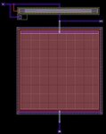
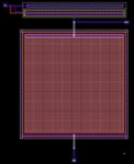
Do you guys know how to draw the layout of a diode? The tool I use is Cadence and the process is AMS c35b4. The diodes in the "PRIMLIB" do not have the layout with them.

Many thanks.
 

If common substrate is P- then,
1. Put a N-WELL
2. Place two rectangles of active (diffusion layer) side by side.
(The area of the recangle should be equal to area of diode).

3. Then cover one of the active with TAP layer to invert the diffusion type.
4. Place diffusion contacts on both the diffusion areas.
5. Rectangle covered with TAP layer is N terminal of diode and the other rectangle is P terminal of diode.
 

Hi,

First find out which diode you need for your design.?
There are many types of diodes, Ndiode, PDiode, Nwell Diode, DeepNwell Diode, RF Diodes, native diodes, Schottkey Diode etc. Again in some of this like Normal Ndiode and Pdiode we have lowVT high VT, medium VT diodes. Again in some designs we need overdrive and underdrive capability diodes.
See what type of diodes your Process and technology nodes support from DRM( Design rule Manual) given by the foundry. and then find out what are all the specific layers you need for the specific diode layout from your DRM. There are different layers like VTH_N, VTL_N, VTH_P, VTL_P layers also for different vt devices. Similarly there are NT_N fabrication layers for native diodes.

The Layout of each one of the above diodes differs!!!!.

Please Note : Different Process types: Low Power, general Purpose etc.

If you get back which diode you actually need, we can tell how to draw the layout.

Thanks
vlsi123
 
Be aware that diodes in a JI well are really BJTs, and need
to be persuaded to not act like one. You might do well to
draw out the vertical cross-section and the range of
potentials on each region, and be sure you have a full grasp
of what might go wrong. I've seen "CMOS-only" guys get
surprised that way.
 

Thanks for your replies. I am doing the layout of a Charge-pump. I decide to use a PMOS with the gate connected to its source (diode fashion). The bulk is also connected to its source to reduce body effect. I draw a circuit of 1 diode fashion PMOS and 1 capacitor. Both schematic and layout are attached. I got 3 errors: 2 ERC Warning: Latchup rule LAT3 distance s/d diff pgate net_welltap >20; 1 INFO: hot nwell. I wonder if I am right to do the layout? Can anyone give me some suggestions.
 

Attachments

  • layout.JPG
    layout.JPG
    149.6 KB · Views: 507
  • schematic.JPG
    schematic.JPG
    33.1 KB · Views: 395

Use 10um fingers and a guardring all around the well
periphery. That will nail it down real nicely and you will
not have the ntap errors. "Hot nwell" means it's not
hard tied to a supply I expect, and means you ought
to be checking that its capacitance and any neighbors
that might create a lateral PNP, are well thought out.

If you are not badly pressed for layout area, making
your own transistor cells that include guard-rings (ntap
or ptap) will let you place & hook up without having to
go back and wedge in the taps, while believing that a
20um distant one will really do the job for an abnormal
sort of application (relative to regular CMOS rail-tied
circuitry).

You should consider a synchronous rectifier if you want
a decently efficient charge pump in low input voltage
operation. You'll be eating VT or Vf per stage otherwise,
and that helps none.
 
  • Like
Reactions: kinty

    kinty

    Points: 2
    Helpful Answer Positive Rating
Thanks dick_freebird. The problem of "Latchup rule LAT3 distance s/d diff pgate net_welltap >20" is solved. But I still have the error of hot nwell. I dont have any supply in this simple layout and dont know how to tied the nwell to a supply. Layout is attached.
 

Attachments

  • layout.JPG
    layout.JPG
    153.4 KB · Views: 787

even if its an old thread, i wanna answer about the hot nwell,
i think it can be solved by changing the pins from txt type to pin (M1) type
 

Status
Not open for further replies.

Part and Inventory Search

Welcome to EDABoard.com

Sponsor

Back
Top