Continue to Site

Welcome to EDAboard.com

Welcome to our site! EDAboard.com is an international Electronics Discussion Forum focused on EDA software, circuits, schematics, books, theory, papers, asic, pld, 8051, DSP, Network, RF, Analog Design, PCB, Service Manuals... and a whole lot more! To participate you need to register. Registration is free. Click here to register now.

how to do stb. analysis in constant gm circuit?

Status
Not open for further replies.

coolsummer

Junior Member level 3
Joined
Mar 18, 2019
Messages
28
Helped
0
Reputation
0
Reaction score
0
Trophy points
1
Activity points
477
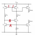
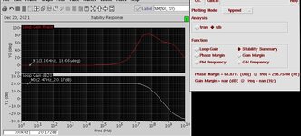
In a Vth reference circuit shown below, do I have to do a stability analysis?I simulated the circuit in virtuoso, and when I break the loop at point A, the loop phase starts from 0°, which means it is a positive feedback; while I break the loop at point B, the loop phase starts from 180°. The results confused me, in such constant gm circuit, how to do stb. analysis or is it possible to do?
 

Attachments

  • a.jpg
    a.jpg
    18.6 KB · Views: 286

do you have more AC sources placed on the schematic? show your testbench and waveforms when you break the loop at node A.
 

do you have more AC sources placed on the schematic? show your testbench and waveforms when you break the loop at node A.
I just insert current probes at point A & B and do stb. simulation, no ac sources. The test bench and results are shown below.
 

Attachments

  • b.JPG
    b.JPG
    255.5 KB · Views: 183
  • c.JPG
    c.JPG
    103.7 KB · Views: 159

strange. did you see similar behavior under PVT variation? in all corners it produced the same effect?
I have seen similar with an other circuit once ago, the solution there was to connect most of the devices bulk terminal to its source, which eliminated AC bulk control, small signal model of transistors can cheat. I recommend you to try that.
Otherwise I would believe option B results if phase starts from -180deg, and don't worry about oscillation. These regulated gm cells are quite stable, since the follower decreases loop gain and its output resistance small, capacitance negligible.
 

    coolsummer

    Points: 2
    Helpful Answer Positive Rating
Status
Not open for further replies.

Similar threads

Part and Inventory Search

Welcome to EDABoard.com

Sponsor

Back
Top