Continue to Site

Welcome to EDAboard.com

Welcome to our site! EDAboard.com is an international Electronics Discussion Forum focused on EDA software, circuits, schematics, books, theory, papers, asic, pld, 8051, DSP, Network, RF, Analog Design, PCB, Service Manuals... and a whole lot more! To participate you need to register. Registration is free. Click here to register now.

how to design the circuit of transistor with saturation

Status
Not open for further replies.

hero0765

Member level 2
Joined
Sep 15, 2008
Messages
52
Helped
2
Reputation
4
Reaction score
2
Trophy points
1,288
Location
China
Activity points
1,605
transistor beta versus saturation

hi:

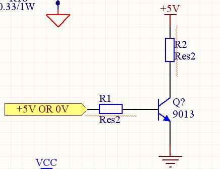
I want to make the transistor into saturation area . In this case , the transistor behave like a switch. I want to decide the resistor values in according with the parameters in the datasheet of 9013. But I don't know which parameters are valuable to me to caculate the resistor values.

fig:
63_1250068539.jpg
 

transistor saturation circuit

Suppose \[Q\] is in SAT. Then \[V_{BE}=V_{\gamma}\] and \[V_{CE}=V_{CE_{SAT}}\]. Now suppose the yellow ribbon is \[5V\]. Then

\[V_{CE_{SAT}}+R_1 i_C=5\]

and

\[V_{\gamma}+R_2 i_B=5\]

If \[Q\] is in SAT, then \[i_C< \beta_F i_B\], so

\[\frac{5-V_{CE_{SAT}}}{R_1}< \beta_F \frac{5-V_{\gamma}}{R_2}\].

Now suppose the yellow ribbon is \[0V\]. Then, by analogous calculations,

\[\frac{5-V_{CE_{SAT}}}{R_1}< -\beta_F \frac{V_{\gamma}}{R_2}\]

I guess this is quite difficult, since you'd need negative \[R_1\].

Added after 2 hours 37 minutes:

This circuit is a RTL inverter.
The value of the output is

(I) \[V_{CC}\] if \[0<v_{\text{IN}}<V_{\gamma}\] (\[Q\] off)

(II) \[V_{CC}-\frac{R_2}{R_1} \beta_F (v_{\text{IN}}-V_{\gamma})\] if \[V_{\gamma}<v_{\text{IN}}<V_{\gamma}+\frac{R_1}{R_2 \beta_F} (V_{CC}-V_{CEsat})\] (\[Q\] normal region)

(III) \[V_{CEsat}\] if \[v_{\text{IN}}>V_{\gamma}+\frac{R_1}{R_2 \beta_F} (V_{CC}-V_{CEsat})\] (\[Q\] SAT)

So in the data-sheet you should search for \[V_{\gamma}\] (threshold voltage), \[V_{CEsat}\] (sat voltage) and \[\beta_F\] (current gain).
 
Last edited by a moderator:

how to design a circuit

I want to know the condition that makes the transistor into saturation area is what?

wheter increase the IB to the sat current , the the transistor into saturation area ?
but if the output current of my micorcontroller's I/O pin is less than 20mA, and the IB sat current of the transistor is more than 50mA, how should I do?
 

transistor saturation

What are the two letters preceding the number 9013 of the transistor?

A 2N3904 has a max saturation voltage loss of 0.2V when its collector current is 10mA and its base current is 1mA, even if its beta is 100 or more.
Beta is not used for calculating the base current of saturated transistors.

If you have a transistor that needs a base current of 50mA but your micro-controller can supply only 20mA then use a darlington transistor that uses a much lower base current. Or if you don't want the extra voltage loss of a darlington transistor then use a Mosfet or a logic-level Mosfet.
 

Status
Not open for further replies.

Part and Inventory Search

Welcome to EDABoard.com

Sponsor

Back
Top