Continue to Site

Welcome to EDAboard.com

Welcome to our site! EDAboard.com is an international Electronics Discussion Forum focused on EDA software, circuits, schematics, books, theory, papers, asic, pld, 8051, DSP, Network, RF, Analog Design, PCB, Service Manuals... and a whole lot more! To participate you need to register. Registration is free. Click here to register now.

How to design Sallen Key Filter with gain

Status
Not open for further replies.

habibparacha

Junior Member level 2
Joined
Oct 25, 2010
Messages
24
Helped
1
Reputation
2
Reaction score
1
Trophy points
1,283
Activity points
1,482
Hi,

How can I set the gain of the Sallen key filter?
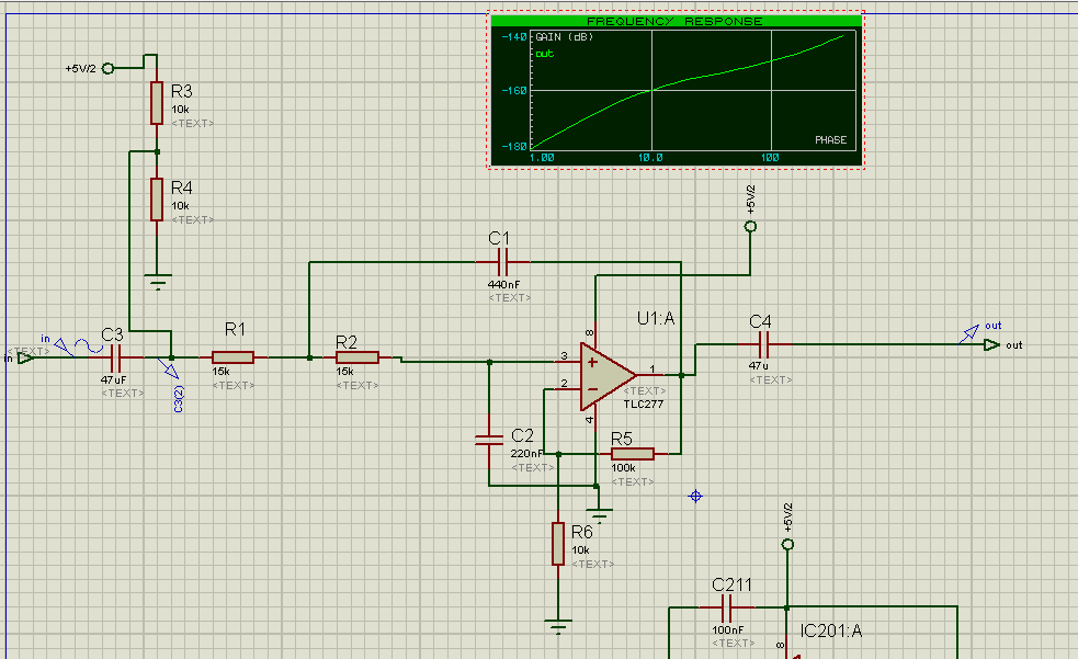
I am designing a low pass 2nd order filter at frequency of 34Hz. But it works in the unity gain configuration when I try to give it gain with Ra and Rb the circuit gets unstable. Can someone suggest how can I give gain to that filter?
I am using the single supply configuration.

here is the schematic
http://obrazki.elektroda.pl/20_1324968273.png


In a rough estimation, the value of C1 has to be reduced by the gain factor.
 

Habibparacha,
some general remarks to the Sallen-Key topology:

SK filter are very sensitive to gain variations resp. gain uncertainties due to tolerances.
Therefore, three design strategies are preferred:
* Equal components (R1=R2, C1=C2) resulting in an opamp gain G=3-1/Qp (Qp=quality factor).
Don't use this structure for Qp>1 because of severe tolerance influence.
* Fixed gain G=2 (two equal valued gain fixing resistors) and C1=C2 and R1/R2=k=Qp^2
* Fixed gain G=1 (unity gain with 100% negative feedback)

In general, if you need gain use a second opamp gain stage (or another filter topology providing gain).

---------- Post added at 11:23 ---------- Previous post was at 11:19 ----------

Applying single supply instead of split supply is another issue. Don't forget that in this case the dc gain of the opamp needs to be unity (in order to transfer the dc bias from the positive input terminal to the output)!
 
Positive feed back adds gain to the filter, Try to modify C1 as told by FVM
 

Positive feed back adds gain to the filter, Try to modify C1 as told by FVM

I do not recommend this "strategy". It is far from being an engineering design - rather it is a "trial and error" procedure (pole Q and pole frequency are both altered)
 

In fact I didn't want to suggest a design method. I only wanted to tell an order of magnitude for C1 to keep the filter parameters with additional gain. To implement a specific filter prototype, e.g. butterworth that seems to be intended by the original poster, you would perform an exact calculation of all filter components.

I also didn't discuss component parameter sensitivity. I completely agree with LvW, that the increased sensitive against gain or time constant variations is a strong argument against Sallen Key topology with gain > 2 or 3. You'll be able to get 1% tolerated resistors, but C1 tolerance will be an issue.

A possible workaround for lower filter frequencies is to use low impedance gain set resistors and connect C1 to inverting input instead of OP output, with original G=1 RC parameters. Of course, there's a certain feed forward effect, you have to decide, if it can be tolerated.

As LvW explained, the DC gain has to be considered as well, the original circuit from post #1 didn't.
 

Status
Not open for further replies.

Part and Inventory Search

Welcome to EDABoard.com

Sponsor

Back
Top