Continue to Site

Welcome to EDAboard.com

Welcome to our site! EDAboard.com is an international Electronics Discussion Forum focused on EDA software, circuits, schematics, books, theory, papers, asic, pld, 8051, DSP, Network, RF, Analog Design, PCB, Service Manuals... and a whole lot more! To participate you need to register. Registration is free. Click here to register now.

How to design a Microcontroller interface with RS232 and 555 timer

Status
Not open for further replies.

pikashi

Newbie level 6
Joined
Sep 4, 2010
Messages
11
Helped
0
Reputation
0
Reaction score
0
Trophy points
1,281
Activity points
1,409
Hi all,

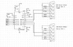
Can anyone help me with this. I am using DS89C450 microcontroller chip and I would like to connect up with RS232 (dB9) and Max232 but I do not know how to interface them to make it work. Next, I would like to make the Microcontroller output to connect to 10 x NE555 timer so that I can control my relay. Please advise me how to connect them. Thank you.
 

Hi,
1) as for interfacing the 8051 using RS232 check any 8051 related book(mazadi could be a good one)/ or just google it out.
2) For controlling the realys why do u need NE555 ? Whats the purpose you are trying to achive? I guess you are getting the basics wrong!!!!

Asimov
 

1) figure out how to make a rs232 work;
2) figure out how to control a 555;
3) put it all together.

---------- Post added at 04:52 PM ---------- Previous post was at 04:51 PM ----------

Whats the purpose you are trying to achive?

likely as a relay driver.
 

Just to complement what millwood wrote. Just take a look at MAX232 datasheet. The schematic is very straightforward. For 555 again i would sugest you to read the datasheet to understand how it does works. Its very simple. If you already have some expereince with microcontrolers you can write down a circuit in one day of work easily. If you have any doubts, first try making yourself a schematic and post here. No one is going to make that for you, but we can say if it is going to work or not.
 

Hi all, thank for your reply.

I am not quite sure what am I doing also as I am new to it and this is my project. But my main criteria is to make the Ds89C450 controller to interface with RS232 and MAX232 so that It can communicated with the PC and I can Program my chip. Next, from the microcontroller, I need at least 14 I/O to control my Multiplexer, timer and etc. Do you guys have the programming code so that I can program my chip? Thanks for you kind help.
 

To program the DS89C450 you need MTK (mocrocontroller-tool-kit) ..
It can be downloaded from:

**broken link removed**

Info on how to connect MAX232 and DB9 (loader port) is on the attached picture ..

IanP
:grin:
 

Attachments

  • DS89C450_and_Max232_x_2_FT0_controller-p2_.jpg
    DS89C450_and_Max232_x_2_FT0_controller-p2_.jpg
    32.6 KB · Views: 133

Hi,
What the objective or the problem statement of your project?

Asimov
 

I am not quite sure what am I doing

sounds like the first order of business is for you to figure that out.
 

Hi guys, I have posted the schemetic drawing for Microcontroller to interface with PC so that I can program it. But i encounter problem with unable to establish connection between PC to Microcontroller. Can any one help me?

---------- Post added at 00:12 ---------- Previous post was at 00:10 ----------

This is the schemetic drawing. Do let me know if anything goes wrong. https://obrazki.elektroda.pl/59_1284739672.jpg

---------- Post added at 00:14 ---------- Previous post was at 00:12 ----------

The cable to use for PC RS232 to Microcontroller Serier Port is Straight or Cross cable? Thanks everyone.
 

where it marks RS232 PC TD must be pin 3 of COM9 (on PC you can use a straight cable to extend it) RD must be pin 2 and you need also pin 5 from DB9 as Ground.... (DTR is PIN 4 of COM9)
 

Status
Not open for further replies.

Part and Inventory Search

Welcome to EDABoard.com

Sponsor

Back
Top