luckyali
Member level 5
dear all
I dont know if this is the right place to post such kind of Thread, but if some one can suggest the right place to ask for help in circuit designing.
well in our university we have to make a project for getting some credit point. out of some topics list I selected " Ultra-wideband IQ up-donw- converter", whose description is
• to concept
• to design
• to implement, and
• to test
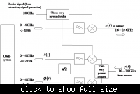
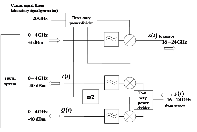
a direct up-down converter which extends the operational band of an ultra-wideband-baseband system to the 20 GHz band. The circuit has to be implemented at double sided RF PCB-materials (preferentially from Rogers). The PCB will be manufactured by the specifications of the student. software's like HFSS, ADS and CST can be used for simulation purpose. suggestions are welcome which one is best for this purpose..
the conceptual circuit is attached with this msg.
Since I am new to Electronic Circuit designs I would like to know what step should be taken in designing this circuit.
Best Regards
I dont know if this is the right place to post such kind of Thread, but if some one can suggest the right place to ask for help in circuit designing.
well in our university we have to make a project for getting some credit point. out of some topics list I selected " Ultra-wideband IQ up-donw- converter", whose description is
• to concept
• to design
• to implement, and
• to test
a direct up-down converter which extends the operational band of an ultra-wideband-baseband system to the 20 GHz band. The circuit has to be implemented at double sided RF PCB-materials (preferentially from Rogers). The PCB will be manufactured by the specifications of the student. software's like HFSS, ADS and CST can be used for simulation purpose. suggestions are welcome which one is best for this purpose..
the conceptual circuit is attached with this msg.
Since I am new to Electronic Circuit designs I would like to know what step should be taken in designing this circuit.
Best Regards