Welcome to our site! EDAboard.com is an international Electronics Discussion Forum focused on EDA software, circuits, schematics, books, theory, papers, asic, pld, 8051, DSP, Network, RF, Analog Design, PCB, Service Manuals... and a whole lot more! To participate you need to register. Registration is free. Click here to register now.
In order to avoid the insertion loss described by tony_lth, I've had moderate success by using a frequency selective splitter/combiner - a diplexer - to firstly split the signals into 2 BPF's, and then recombine them afterwards.
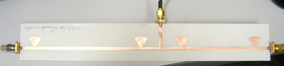
Beginning with the disclaimer that it's not a polished solution(!), I ported the concept of the "stub tuner diplexer" (described in **broken link removed**) to where I needed it at 2.4 GHz. I then used ADS to optimise my structure for the (excessively thick) substrate I had to hand and used a PCB mill to create the final diplexer:
It offers ~15 dB of isolation between my two frequencies (only 40 MHz apart) at either port, with an insertion loss of ~1 dB (mainly due to microstrip radiation loss).
Combined with (cheap) commercially available filters (https://www.l-com.com/familylist.aspx?id=3019), it allows for pretty vicious filtering of two ISM band frequencies!
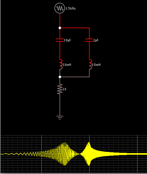
If you just connect the two bandpass filters in parallel, the input matching will be bad because you will see the stopband input impedance of one filter in parallel to the passband input impedance of the other filter.
Depending on the frequency spacing between the two band, you can use a diplexer (frequency splitter) to separate and combine the two channels. This avoids the 3+3dB power splitter loss that Tony mentioned.
This site uses cookies to help personalise content, tailor your experience and to keep you logged in if you register.
By continuing to use this site, you are consenting to our use of cookies.