Welcome to our site! EDAboard.com is an international Electronics Discussion Forum focused on EDA software, circuits, schematics, books, theory, papers, asic, pld, 8051, DSP, Network, RF, Analog Design, PCB, Service Manuals... and a whole lot more! To participate you need to register. Registration is free. Click here to register now.
Hi plusminus,
Yes for the first version of the design i will recover the clock from a serial Manchester Coded signal. For the second version, and in the hope of reducing power due to switching activity, the recovery will be from a NRZ coded signal.
Added after 2 hours 50 minutes:
VHDL will be used as specification language. Please teel me how to proceed.
Your question on how do I proceed tells me that you dont truly understand the basics of Manchester or NRZ encoding. If you did then you would understand how to pull the clock signal from either encoding method.
Take sometime and do some research before you start a project like that.
In fact I am new in this domain. That I wanna know is to understant the recovery principle. The thing that i couldn't understand is how to generate the clock from a signal when there we hava a sequece of '1' or '0'. You can consider the worst case obtained in a simple non coded signal.
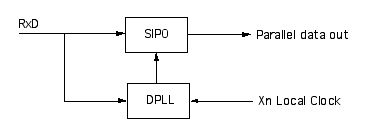
The total story is a bit to long to explain but in essence it works like this:
At the transmitter side you multiplex the bitstream data with a clock ( exor ).
At the receiver side you can extract the data and clock by a (D)PLL circuit.
This site uses cookies to help personalise content, tailor your experience and to keep you logged in if you register.
By continuing to use this site, you are consenting to our use of cookies.