Continue to Site

Welcome to EDAboard.com

Welcome to our site! EDAboard.com is an international Electronics Discussion Forum focused on EDA software, circuits, schematics, books, theory, papers, asic, pld, 8051, DSP, Network, RF, Analog Design, PCB, Service Manuals... and a whole lot more! To participate you need to register. Registration is free. Click here to register now.

How to Decrease Wattage

Status
Not open for further replies.

mromrell

Newbie level 3
Joined
Jan 17, 2012
Messages
4
Helped
0
Reputation
0
Reaction score
0
Trophy points
1,281
Activity points
1,321
I'm new to this Forum but my friends tell me that you guys are awesome!
So here's the deal: I am building electric hand heaters for my motorcycle and I need some verification that I'm doing this properly. My bike puts out 14 volts and 700 watts total. I want to run these heaters at 30 watts. (below is my basic schematic.)
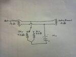
IMG866.jpg

My calculations tell me that I need a 5.5 ohm resistor for the 30 watt
Would that resistor need to be rated at 700 W? or 30 W?
If it needs to be rated at 700 W, then how would I lower the wattage to that circuit so that it operated at 30 W?

My other assumptions are:
30w/14Volts = 2.14 Amps
14volts/2.14 Amps = 6.53 Ω needed throughout the circuit.
since 10 ft of 30 gauge heating wire amounts to 1.03 Ω then
6.53 Ω - 1.03 Ω = 5.5 Ω Resistor that needs to be added to the circuit.

Does that look like it would work?


:-o Thank you for your help!!!! :smile:
 

10 /10 ! well done. The 5.5 ohms resistor needs to be rated at 30W (its carrying 2.14 A @ 5.5 ( ~12V) 12 X 2.14 ~ 25W). Can't you wind your finger heaters with thinner wire so their resistance goes up, the external resistor goes down and you waste less power in it?
Frank
 

The the resistor will have to be rated at 30W + 20%...
But you can't choose any resistor for such an application...It can't be very large - because then it'll dissipate the heat too fast. On the other hand, it can't be very small because it will become too hot.

I think that a nichrome wire (at the correct gauge) wili work better than a discrete resistor...

Good Luck!
 

Awesome! Thanks for the help! So I don't need to do anything special to adjust the wattage down from 700w? I am assuming circuits simply automatically adjust the wattage according to the resistance and voltage I put into it Is that Correct?

And my follow up question would be: If I get a 5 ohm 30w resistor and add a .5 ohm resistor in series, would the .5 ohm resistor also need to be rated at 30w?
 

The problem with your circuit is, that nearly all power is disspated in the resistor and only a small amount of power in the heating elements, in other words, there is nearly no heating effect where you want it. If about 0.5 W per heater is sufficient, the circuit will be O.K. Otherwise, you'll want to design a heating element with higher resistance, that get's a larger share of the total power.
 

Awesome! Thanks for the help! So I don't need to do anything special to adjust the wattage down from 700w? I am assuming circuits simply automatically adjust the wattage according to the resistance and voltage I put into it Is that Correct?
Correct.

And my follow up question would be: If I get a 5 ohm 30w resistor and add a .5 ohm resistor in series, would the .5 ohm resistor also need to be rated at 30w?
No, it needs to be rated for only 3W.

However, I suggest you pay attention to the point raised by FvM. With the current scheme, you're wasting about 84% of the 30W on the dropping (or power-reducing) resistor and less than 5W will go towards warming your hands.
 
No, it needs to be rated for only 3W.

Or even less, referring to the resistance values and circuit shown in post 1. schematic. It's two 0.5 ohms heaters in parallel, or 0.25 ohm total. Gives 0.6 V for heaters with 14V alternator voltage, or 0.75 W each. A more reasonable series connection of both heaters gives already 15% of total power to the heaters.
 

The problem with your circuit is, that nearly all power is disspated in the resistor and only a small amount of power in the heating elements, in other words, there is nearly no heating effect where you want it. If about 0.5 W per heater is sufficient, the circuit will be O.K. Otherwise, you'll want to design a heating element with higher resistance, that get's a larger share of the total power.

Alright, So I would need to decrease the resistance from the resistors to increase the wattage per heater.
And, correct me if i'm wrong, but since 30 gauge wire maxes out at 0.86 amps (according to this chart: American Wire Gauge table and AWG Electrical Current Load Limits with skin depth frequencies).
How would I get the majority of the wattage passing through the heating elements without going over that amperage restriction?
 

There's a chance you can use the nichrome element from an electric blanket. Or similar.

You would need a few feet in order to wind one or more layers around the handgrips.

You'll need to contrive a suitable connection because nichrome does not adhere to solder.
 

I didn't notice yet, that your calculations have been for copper wire. I agree with BradtheRad, that it would be more reasonable to use resistance wire. Due to the higher resistivity, it has larger diameter and surface for a particular resistance and thus better heat transmission to the surrounding material.
 
Bummer. I really wanted to aviod using a different kind of wire since I already sewed in 10 feet of 30 gauge teflon coated, high temp, silver-plated copper.
Is that going to be the only way to get useable heat from this thing?
 

Alright, So I would need to decrease the resistance from the resistors to increase the wattage per heater.
And, correct me if i'm wrong, but since 30 gauge wire maxes out at 0.86 amps (according to this chart: American Wire Gauge table and AWG Electrical Current Load Limits with skin depth frequencies).
How would I get the majority of the wattage passing through the heating elements without going over that amperage restriction?

You can't unless you have parallel paths. At 0.86A you are limited to 0.86A*0.86A*0.25ohms = 185mW of power to the heaters.
Do you really need 30W of heat? I could be wrong, but this seems like way too much heat for hand heaters. Might melt your fingers too the handles!
If you connected the heaters in series instead of parallel you could deliver 24.5W to each heater by simply connecting the ~ 1 ohm of 30 gauge wire directly without resistors ( if not for the fact that 30G wire will not handle 7A of current ) => 14V*14V/2 ohms = 98 W => about 49W across the heaters => 24.5W for each heater
2 ohms = 0.5 ohm + 0.5 ohm + 1 ohm ( wire )
Current would be I=14V/2 ohms = 7A

Your initial calculations were assuming that all the 14V supply power would be delivered to the heaters. But then you added in the resistors which actually consumed most of the power. So in fact, you were consuming 30W of power from the battery. But more than 29W was actually getting burned by the resistors' power dissipation. A better way to make this calculation would have been to use P=I^2*R since the resistance and power is known. I=SQRT(P/R) = SQRT(30W/0.5ohms) = 7.75A => so you would need 7.75A through EACH heater to give 30W to each heater. Immediately you would see that this is a problem with 30G wire.

I stand corrected! It seems that 30W is a standard value for motorcycle handgrips :-o
 
Last edited:

I don't have much to add to the detailed explanation of DartPlayer170. One point is that the 0.86 A rating doesn't necessarily apply for your teflon coated wire. It's a standard rating based on prerequisites. In your case, you want to assure that the conductor temperature doesn't exceed the continuous operation temperature of the teflon insulation, which is about 250 °C.

Teflon insulated resistance wires of different gauge are frequently used for industrial heating applications, e.g. trace heating, but may be hard to get anyway.
 

The heating element in electric socks is another idea. Could serve as a guideline anyway.

Mine has a single conductive strip under the toes. Powered by a 1.5V D cell. Conducts .2 amps. This works out to 7.5 ohm resistance.

Power consumed (as heat) is 300mW. It doesn't sound like a lot but it's in a confined space. So it can keep toes warm.

The same heating element might burn up if 14 V were applied. So you would need an element with resistance on the order of 100 ohms. On each handgrip.

Since it's in open air you probably need a few watts. Say 50 ohm elements per handgrip.

It may be better to use 2 or 3 straight elements across the handgrips, rather than to wrap wire around the handgrip. If you make windings around the handgrip it will become a slippery texture. In time the windings could unravel at an unpredictable moment.

To make such elements you might try dismantling a toaster. I don't know what resistance the element has per inch. However you will have encase it in something to protect it, yet also let heat pass through it. It will take some experimentation.
 

Status
Not open for further replies.

Similar threads

Part and Inventory Search

Welcome to EDABoard.com

Sponsor

Back
Top