Continue to Site

Welcome to EDAboard.com

Welcome to our site! EDAboard.com is an international Electronics Discussion Forum focused on EDA software, circuits, schematics, books, theory, papers, asic, pld, 8051, DSP, Network, RF, Analog Design, PCB, Service Manuals... and a whole lot more! To participate you need to register. Registration is free. Click here to register now.

How to convert voltage -5V to +5V to a range of 0-5v

Status
Not open for further replies.

garfy

Newbie level 4
Joined
Apr 3, 2009
Messages
5
Helped
0
Reputation
0
Reaction score
0
Trophy points
1,281
Activity points
1,322
I have an inclinometer that outputs a range of -5 to +5v. The output of the inclinometer will be fed to my PIC that can only takes in positive voltage in the range of 0-5V.

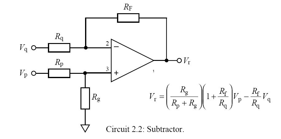
I have the following circuit as shown in the attachment. The gain of the op amp is --0.5 in this case.

When I put Vin to Ground, Vout has a voltage of 3.75V. When I put Vin to 5v, Vout measures 1.24V from the voltmeter. Why isn't the voltage 2.50V and 0V respectively. The op amp i'm using is LM358. I'm prototyping on breadboard.

I am new to op amp, would appreciate any help. Thanks!
 

When vin = 0.
The gain of this amp is =(1+(R/2R)) = 1.5
 

The gain is ΔVout/ΔVin, and it's -R/2R or -0.5, as said. But the bias voltage at +In has to be 1.67 rather than 2.5 V for intended operation, so the voltage divider must be 2R:R instead of R:R.
 

U are right, the voltage divder should be 2R:R, based on the calculation.

So, i use the following resistor values,
Rg = 10K, Rp = 20K, Rq = 20K, Rf = 10K, Vp = 5V

Vcc = 5V (LM358)
Vcc- = 0V

With the above calculation, i should get the following Vr based on the Vq value.
Vq = 0, Vr = 2.5v, Vr (voltmeter) = 2.5v (OK)
Vq = 5v, Vr = 0v, Vr (voltmeter) = 0.62v (Wrong!)

When Vq = 5v, my voltmeter gives me 0.62v, which is incorrect. I have checked my connection, even did 2 prototype separately. Both gave the same voltmeter readings.

When I replace Rp by 10K (in the above circuit), i got the right Vr value.
Vq = 0, Vr = 3.75v, Vr (voltmeter) = 3.75v (OK)
Vq = 5v, Vr = 1.25v, Vr ( voltmeter) = 1.24v (OK)

Can somebody enlighten me on this? why is there a discrepancy?

Am i missing out something that i do not know, i checked the LM358 datasheet... everything seems to be OK...

I'm using resistors of 1% tolerance, 0.25W.


Help....
 

LM358 doesn't work for this design because it's not rail-to-rail output. It almost reaches V- but, if I remember right, about 3.5 V Vout,max. There's a rich choice of RtoR output OP's, e.g. TLV271 or many Microchip MCPxx types.
 

    garfy

    Points: 2
    Helpful Answer Positive Rating
FvM said:
LM358 doesn't work for this design because it's not rail-to-rail output. It almost reaches V- but, if I remember right, about 3.5 V Vout,max. There's a rich choice of RtoR output OP's, e.g. TLV271 or many Microchip MCPxx types.

Thanks, just as i have suspected. I will look for another op amp. :)
 

Status
Not open for further replies.

Part and Inventory Search

Welcome to EDABoard.com

Sponsor

Back
Top