Continue to Site

Welcome to EDAboard.com

Welcome to our site! EDAboard.com is an international Electronics Discussion Forum focused on EDA software, circuits, schematics, books, theory, papers, asic, pld, 8051, DSP, Network, RF, Analog Design, PCB, Service Manuals... and a whole lot more! To participate you need to register. Registration is free. Click here to register now.

how to configured pic16f676 in micro c pro compiler

Status
Not open for further replies.
You can't change the config bits in config window. When you set Oscillator type, WDT settings, etc... in Project > Edit Project... dialog box then config bits are generated.
 

Attachments

  • config2.png
    config2.png
    24 KB · Views: 98

hello swapan in setting you said
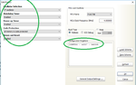
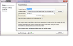
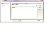
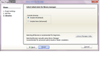
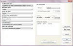
also check the box against "Open Edit Project Window to set configuration bits" and finally hit Next) - Next - Next - i din't found ,please tell me again step by step setting config
please

After opening mikroC click on Project which is on the top. then click on New Project in the dropdown list. Then a new window will be opened. A screenshot (Conf_1) is given. see it.

You can see 5 items are there starting from Project Name, Project Folder, Device Name, Device clock and at the last "Open Edit Project Window to set configuration bits". On the left side of the item one Box is there. If it is ticked then alright, otherwisw tick it. Now click Next.

Another window will be opened as New Project Wizard (see screenshor as Conf_2) . You just do nothing and click Next.

Here also you do nothing and click Next (see screenshot as Conf_3).
Now Project Editor window will be opened (See the screenshot as Conf_4). Here you can set configuration bit settings.
See the window. on the left side there are 7 boxes having one downward arrow against each.
Click on these arrows and choose the desired settings.
On the right side in the box "MCU and Oscillator" check if your selected device like 16F676 is shown. If you use internal oscillator then edit the MCU clock Frequency [MHz] as 4.000000.
Click on OK.
Have any more query - ask again.
 

Attachments

  • Conf_1.png
    Conf_1.png
    55.6 KB · Views: 89
  • Conf_2.png
    Conf_2.png
    47.8 KB · Views: 95
  • Conf_3.png
    Conf_3.png
    51.6 KB · Views: 89
  • Conf_4.png
    Conf_4.png
    54.3 KB · Views: 82
Last edited:
thank u all of you ,specially okara and swapan.

- - - Updated - - -

HI OKARA MY HEX CODE IS ONLY 2 BIT DIFFER FOR YOU I ATTACHED MY HEX AND FIND THAT PROBLEM .I TRY TO ALL THINGS BUT NOT CORRECT HEX FILE
THIS IS MY HEX CODE-
:020000001528C1
:0C000600831221088A00200882000800F4
:1000120003208A110A128000840AA00A0319A10A85
:08002200D003031D09280800AA
:10002A000730831299008316910187018312870191
:10003A0087090330DB008A30DC005530DD00DD0B38
:10004A002428DC0B2428DB0B2428000000001D28B0
:02005A002D284F
:02400E00F4318B
:00000001FF


AND THIS IS YOUR HES CODE AND IT IS SAME SOURRCE CODE-
:020000001528C1
:0C000600831221088A00200882000800F4
:1000120003208A110A128000840AA00A0319A10A85
:08002200D003031D09280800AA
:10002A000730831299008316910187018312870191
:10003A0087090330DB008A30DC005530DD00DD0B38
:10004A002428DC0B2428DB0B2428000000001D28B0
:02005A002D284F
:02400E00D431AB
:00000001FF
 

In the screenshots in post #22, it shows the device is a PIC12F675 and in post #21 the device is shown as a PIC16C73B.
Can I suggest that you use the same device in your examples that the OP says he is using.
Also the difference the OP is referring to in the HEX files is probably for the CONFIG word which may well depend on the actual device the compiler thinks it is generating code for.
Susan

The screenshot under post #22 has been given merely as example and not strictly conforming to the project of OP. It is also my doubt if the guy compiled the code with proper configuration settings.
 
Last edited:

hello swapan give a demo of pic16f676 microcontroller all setting with screen shot please

- - - Updated - - -

hello Swapan give a demo of pic16f676 microcontroller all setting with screen shot please

- - - Updated - - -

hi everyone i have problem ,i am writting seven segment source code but in hardware show other things like 0 instead of 1segment blink ,i think not proper config set please help me
 

As you do not respond, it is not understood if you have been able to configure the device properly. Have you found the steps that I described in earlier posts? If so, it will not be difficult for you to do all settings of any MCU.

Show your code for 7 segment display alongwith schematic. Without these it is not possible to debug.
 
hello okada,
I just copied your code and compiled it on my compiler.When I saw content of hex file gererated by my compiler and compared it to hex file content of yours......it is little bit different.Here I am pasting content of your hex file.

:020000001528C1
:0C000600831221088A00200882000800F4
:1000120003208A110A128000840AA00A0319A10A85
:08002200D003031D09280800AA
:10002A000730831299008316910187018312870191
:10003A0087090330DB008A30DC005530DD00DD0B38
:10004A002428DC0B2428DB0B2428000000001D28B0
:02005A002D284F
:02400E00D431AB
:00000001FF

And content of my hex file..

:020000001528C1
:0C000600831221088A00200882000800F4
:1000120003208A110A128000840AA00A0319A10A85
:08002200D003031D09280800AA
:10002A000730831299008316910187018312870191
:10003A0087090330DB008A30DC005530DD00DD0B38
:10004A002428DC0B2428DB0B2428000000001D28B0
:02005A002D284F
:02400E00F2318D
:00000001FF


Here we can see the second last line of both is differ from each other.
While your code is working correctly and mine code not.
One thing i didn't mensioned that I am trying to use internal oscillator of micro.There is no external osc. in my hardware. Is it due to this??
Please help me.......
 

I had used external Oscillator.
 

It is detected that you have chosen "HS Oscillator" which has resulted your .hex file. You just select "INTOSC oscillator :IO function on RA4/OSC2/CLKOUT pin, IO function on RA5/OSC1/CLKIN pin" instead of "HS oscillator", build it, burn the MCU and see the working in hardware. Rest is alright.

NB: Your .hex file that does not work now will surely work if you use external oscillator i.e. crystal of 4 MHh or so in your hardware. Get a trial.
 
hello swapan please help me ,
i tried all things as you said but not working exacty, please guide me
 

What programming software are you using to burn the .hex file ? See if you have to set the config bits manually in your burning software.
 
hi,
i am sending config set as you said.

Capture.PNG

I have already done. Tell me if i am somewhere wrong.
 

Which programmer and programming software are you using to burn the .hex file ?

I see that MCLR is enabled. Either disable it or if you want the reset circuit then pull-up MCLR pin to 5V using 10k resistor otherwise your project will not work.
 
Finally got the same output....
After selecting INTOSC oscillator :IO function on RA4/OSC2/CLKOUT
and disabling MCLR i got same .hex file.
Thanku Okada and swapan....
 

Finally got the same output....
After selecting INTOSC oscillator :IO function on RA4/OSC2/CLKOUT
and disabling MCLR i got same .hex file.
Thanku Okada and swapan....

So your compiler is not faulty and you need not to buy a new compiler, right?
 

I had used external Oscillator.

It is seen that your .hex file in post #10 has been generated using INT oscillator not external oscillator, and hence that .hex file worked. See the .hex file generated using INT oscillator and HS oscillator.

This is .hex using INT oscillator


:020000001528C1
:0C000600831221088A00200882000800F4
:1000120003208A110A128000840AA00A0319A10A85
:08002200D003031D09280800AA
:10002A000730831299008316910187018312870191
:10003A0087090330DB008A30DC005530DD00DD0B38
:10004A002428DC0B2428DB0B2428000000001D28B0
:02005A002D284F
:02400E00D431AB
:00000001FF


This is .hex file using HS oscillator.

:020000001528C1
:0C000600831221088A00200882000800F4
:1000120003208A110A128000840AA00A0319A10A85
:08002200D003031D09280800AA
:10002A000730831299008316910187018312870191
:10003A0087090330DB008A30DC005530DD00DD0B38
:10004A002428DC0B2428DB0B2428000000001D28B0
:02005A002D284F
:02400E00D231AD
:00000001FF


And this is .hex file you have uploaded in post #10..

:020000001528C1
:0C000600831221088A00200882000800F4
:1000120003208A110A128000840AA00A0319A10A85
:08002200D003031D09280800AA
:10002A000730831299008316910187018312870191
:10003A0087090330DB008A30DC005530DD00DD0B38
:10004A002428DC0B2428DB0B2428000000001D28B0
:02005A002D284F
:02400E00D431AB
:00000001FF
 
HELLO SWAPAN and OKADA ,
i am working on pic 16f676 ADC program with output on 2 common cathod 7 segment in my hardware internal oscillator is used,i i write my program according this pin where am i wrong please tell me

vdd |1 14| vss
segment g|2 13| Analog input
segment f |3 12| common cathod(cc_2)
MCLR|4 11| common cathod(cc_1)
segment a|5 10|segment c
segment b|6 9|segment e
segment d |7 8|segment dp


Code:
#define pin_a PORTC.RC5
#define pin_2a PORTA.RA4
#define pin_b PORTC.RC4
#define pin_2b PORTA.RA5
#define pin_c PORTC.RC0
#define pin_2c PORTC.RC3
#define pin_d PORTC.RC3
#define pin_2d PORTC.RC0
#define pin_e PORTC.RC1
#define pin_2e PORTC.RC2
#define pin_f PORTA.RA4
#define pin_2f PORTC.RC5
#define pin_g PORTA.RA5
#define pin_2g PORTC.RC4
#define pin_dp PORTC.RC2
#define pin_2dp PORTC.RC1
#define cc_1 PORTA.RA2
#define cc_2 PORTA.RA1


unsigned char unit,dec,hun,i,j,value=0;

void display()
{
switch(unit)
{
case 0:   pin_a=1;pin_b=1;pin_c=1;pin_d=1;pin_e=1;pin_f=1;pin_g=0;pin_dp=1;
          break;
case 1:   pin_a=0;pin_b=1;pin_c=1;pin_d=0;pin_e=0;pin_f=0;pin_g=0;pin_dp=1;
          break;
case 2:   pin_a=1;pin_b=1;pin_c=0;pin_d=1;pin_e=1;pin_f=0;pin_g=1;pin_dp=1;
          break;
case 3:   pin_a=1;pin_b=1;pin_c=1;pin_d=1;pin_e=0;pin_f=0;pin_g=1;pin_dp=1;
          break;
case 4:   pin_a=0;pin_b=1;pin_c=1;pin_d=0;pin_e=0;pin_f=1;pin_g=1;pin_dp=1;
          break;
case 5:   pin_a=1;pin_b=0;pin_c=1;pin_d=1;pin_e=0;pin_f=1;pin_g=1;pin_dp=1;
          break;
case 6:   pin_a=1;pin_b=0;pin_c=1;pin_d=1;pin_e=1;pin_f=1;pin_g=1;pin_dp=1;
          break;
case 7:   pin_a=1;pin_b=1;pin_c=1;pin_d=0;pin_e=0;pin_f=0;pin_g=0;pin_dp=1;
          break;
case 8:   pin_a=1;pin_b=1;pin_c=1;pin_d=1;pin_e=1;pin_f=1;pin_g=1;pin_dp=1;
          break;
case 9:   pin_a=1;pin_b=1;pin_c=1;pin_d=1;pin_e=0;pin_f=1;pin_g=1;pin_dp=1;
          break;
  }


}


void display2()
{
switch(dec)
{
case 0:   pin_2a=1;pin_2b=1;pin_2c=1;pin_2d=1;pin_2e=1;pin_2f=1;pin_2g=0;pin_2dp=0;
          break;
case 1:   pin_2a=0;pin_2b=1;pin_2c=1;pin_2d=0;pin_2e=0;pin_2f=0;pin_2g=0;pin_2dp=0;
          break;
case 2:   pin_2a=1;pin_2b=1;pin_2c=0;pin_2d=1;pin_2e=1;pin_2f=0;pin_2g=1;pin_2dp=0;
          break;
case 3:   pin_2a=1;pin_2b=1;pin_2c=1;pin_2d=1;pin_2e=0;pin_2f=0;pin_2g=1;pin_2dp=0;
          break;
case 4:   pin_2a=0;pin_2b=1;pin_2c=1;pin_2d=0;pin_2e=0;pin_2f=1;pin_2g=1;pin_2dp=0;
          break;
case 5:   pin_2a=1;pin_2b=0;pin_2c=1;pin_2d=1;pin_2e=0;pin_2f=1;pin_2g=1;pin_2dp=0;
          break;
case 6:   pin_2a=1;pin_2b=0;pin_2c=1;pin_2d=1;pin_2e=1;pin_2f=1;pin_2g=1;pin_2dp=0;
          break;
case 7:   pin_2a=1;pin_2b=1;pin_2c=1;pin_2d=0;pin_2e=0;pin_2f=0;pin_2g=0;pin_2dp=0;
          break;
case 8:   pin_2a=1;pin_2b=1;pin_2c=1;pin_2d=1;pin_2e=1;pin_2f=1;pin_2g=1;pin_2dp=0;
          break;
case 9:   pin_2a=1;pin_2b=1;pin_2c=1;pin_2d=1;pin_2e=0;pin_2f=1;pin_2g=1;pin_2dp=0;
          break;
  }
}


void main() 
{
  int x;
  CMCON = 0x07;
  TRISA= 0x01;
  TRISC  =0x00;
  ANSEL  = 0X01;
  ADCON0=0X81;
  ADCON1=0X30;

     for(x=0;x<300;x++)
         {
          value = ADCON0;
           hun=value/100;
           value=value-hun*100;
           dec=value/10;
                 unit=value-dec*10;
                   cc_1=1;cc_2=0;
                  display();
                  delay_ms(100);
                  cc_1=0;cc_2=1;
                  display2();
                  delay_ms(100);
            }


          }


i used first 7segment pin as above i told . and i attach my program check and tell me how will i write to print (0to99) for (0to5v)

- - - Updated - - -

please tell me sir what should I do?

- - - Updated - - -

hello swapan sir tell me what should i do ?
 

Please wait. I am very much occupied with another issue. I shall certainly help you to my best.
 
Do you want me to modify your code and make it work or shall I provide you the proper code for driving seven segment displays which uses Timer Interrupts ? That is Multiplexed displays.
 

Status
Not open for further replies.

Part and Inventory Search

Welcome to EDABoard.com

Sponsor

Back
Top