Continue to Site

Welcome to EDAboard.com

Welcome to our site! EDAboard.com is an international Electronics Discussion Forum focused on EDA software, circuits, schematics, books, theory, papers, asic, pld, 8051, DSP, Network, RF, Analog Design, PCB, Service Manuals... and a whole lot more! To participate you need to register. Registration is free. Click here to register now.

How to choose and design op amp to detect and amplify photodiode current

Status
Not open for further replies.

simbaliya

Member level 4
Member level 4
Joined
Feb 1, 2011
Messages
74
Helped
0
Reputation
0
Reaction score
0
Trophy points
1,286
Visit site
Activity points
1,943
I need to use an op amp in transimpedance configuration to detect an current pulse in photodiode.

The current pulse has a pulse width of 2us and period of 100us, how should I choose a proper op amp, and how to design the feedback resistor and capacitor?
 

The minimum current is about 1uA, as for SNR, I do not have the data yet.
 

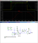
The opamp should be a low input bias current, high frequency type. Below is a simulation of an example circuit with a J-FET opamp (for low input bias current), which gives 2V out for a 1µA input pulse. The values of compensation caps C1 and C3 depend upon the circuit strays and generally need to be experimentally determined after the circuit is built. Source I1 simulates the photo diode current.

If you are interested in simulating the circuit I can download the LTspice .asc simulation file.

Trans Amp.gif
 

Status
Not open for further replies.

Similar threads

Part and Inventory Search

Welcome to EDABoard.com

Sponsor

Back
Top