Continue to Site

Welcome to EDAboard.com

Welcome to our site! EDAboard.com is an international Electronics Discussion Forum focused on EDA software, circuits, schematics, books, theory, papers, asic, pld, 8051, DSP, Network, RF, Analog Design, PCB, Service Manuals... and a whole lot more! To participate you need to register. Registration is free. Click here to register now.

How to check the crystal frequency?

Status
Not open for further replies.

selva murugesan

Advanced Member level 4
Joined
Mar 30, 2012
Messages
116
Helped
2
Reputation
4
Reaction score
1
Trophy points
1,298
Activity points
2,007
Hi

I want to Measure the crystal frequency.the crystal is in the microcontroller mother board.The micro controller is working properly. But I want to know to the way of checking the frequency.I used the CRO 1x probe , but it shows 50 Hz. but I know the crystal is 20Mhz. Any suggestion?
 

Do not measure directly from Crystal legs
You can measure it writing a program to one port of your selected MCU . You can have result well belong to your crystal applying some calculations

Which MCU is using
 

Thanks PA3040.

But my question is , How to check the crystal,whether its working or not? before its soldered in the board.I am using PIC16F877A.
 

Mr. PA3040 is right !
You should check the frequency at its legs so that i can show exactly what freq its producing.
If you check at some other parts, based on your program written the clocks gets distributed and you might assume that the crystal might not be working properly.

- - - Updated - - -

If you measure it as 50 hz instead of 20Mhz before you solder it, then its doesnt work properly. before or after soldering also the way you check is probing at its legs only !
 

Typically, an active scope probe must be employed when probing a crystal directly.

A passive scope probe can significantly alter the oscillation characteristics or even cease oscillation of the crystal under test.


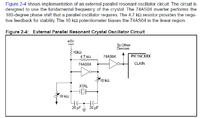
If only a passive scope probe is available and the crystal has not been solder into the design, a simple oscillator circuit like the attached image can be implemented which output will not be significantly altered by a passive scope probe.


If the crystal is already soldered into a design, utilize a software test which toggles a pin at a known ratio to crystal/system clock frequency which can then be monitored by a passive scope probe.

Or

In some case the microcontroller provides a clock output which is a known ratio of the crystal/system clock frequency and this output can be monitored by a passive scope probe.


BigDog
 
  • Like
Reactions: PA3040

    PA3040

    Points: 2
    Helpful Answer Positive Rating
Yes.You can do it Disha.

I used a 1x probe (cro) to measure it.Put one end into the Crystal pin.connect the GND pin into Ground connection.This is my personal experience. I might not see this procedure in any document.The result value is not show in fixed manner. It oscillating.But it shows the sine wave.
 

Status
Not open for further replies.

Part and Inventory Search

Welcome to EDABoard.com

Sponsor

Back
Top