Continue to Site

Welcome to EDAboard.com

Welcome to our site! EDAboard.com is an international Electronics Discussion Forum focused on EDA software, circuits, schematics, books, theory, papers, asic, pld, 8051, DSP, Network, RF, Analog Design, PCB, Service Manuals... and a whole lot more! To participate you need to register. Registration is free. Click here to register now.

how to check signal input(pic16f627a)

Status
Not open for further replies.

wayu_ix

Newbie level 6
Joined
Dec 18, 2010
Messages
12
Helped
0
Reputation
0
Reaction score
0
Trophy points
1,281
Activity points
1,353
hi everybody after i pass first step
i test code for check input status
if input =1
delay 20 sec
and if input still =1
i want set out =1 and delay and stop out put again;

by code

main()
{
TRISA = 0x01;
while(1)
{
start:
while(PORTA.F0==1)
{
delay_ms(20000);
while(PORTA.F0==1)
{
PORTA.F1=1;
delay_ms(3000);
PORTA.F1=0;
while(PORTA.F0==1)
{
}
goto start;
}
}

{
}
}
}

i can sim by proteus it work .
but it can't work on real circuit. why this it?
what different between sim program and real pic.?
i hope you help me agian...thank you.
 

Have you set the configuration fuses?
If you used LVP, is it still in programming mode?
If not configured to be internally connected to supply, have you pulled the reset pin up.
Are you using the same clock frequency as you used in the simulator?

Please try to restructure the program without using the "goto" instruction, you will regret it later!

Brian.
 
Hi,
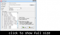
Goto the Project menu and click Edit Project. Project > Edit Project. There set the configuration bits. I think you messed something up over there.

I think you made this mistake. Disable MCLR on RA5 if required. You may not have done this and forgotten to pull it up to +5v. This is usually the difference between what happens in Proteus and real life situation.

If you are using a crystal of less than 8MHz, use "XT" oscillator else use "HS" oscillator.

Turn WDT off.

Turn LVP off unless required.

Since you are new in PIC programming, here's a tip. Always indent your code so that it's easy to understand. You can easily do it in mikroC by pressing "TAB" on your keyboard.
The changed code would look like this:
Code:
main(){
   TRISA = 0x01;
   while(1){
      while(PORTA.F0==1){
         delay_ms(20000);
         while(PORTA.F0==1){
            PORTA.F1=1;
            delay_ms(3000);
            PORTA.F1=0;
            while(PORTA.F0==1){}
         }
      }

   }
}
Much easier to read through.

Hope this helps.
Tahmid.
 
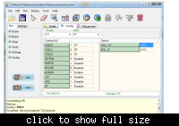
help to check my setting this true.?


XT 4 MHz
i connet serire 10 k resistor between v 5vdc to RA5 ready.
and input use 5 vdc form supply by devider current by 10 k resistor to ground.
this still not work..help me please....
 

Hi,
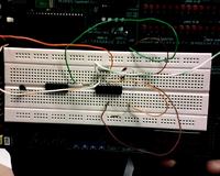
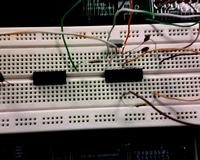
Can you show your hardware? There might be something wrong there.

---------- Post added at 11:07 ---------- Previous post was at 10:26 ----------

Hi,
I think the picture shown is the interface of the programmer. Have you set the same config bits in mikroC? There might be a problem there.

Hope this helps.
Tahmid.


this my hardware can you see detial.?
 

Hi,
What is the value of the resistor from pin 17 to ground?
The hardware looks fine. Have you set the config bits properly in mikroC?
 

Try this:

main()
{
CMCON = 0x07; //comparator must be turned off for digital i/o operation
TRISA = 0x01;
while(1)
{
start:
while(PORTA.F0==1)
{
delay_ms(20000);
while(PORTA.F0==1)
{
PORTA.F1=1;
delay_ms(3000);
PORTA.F1=0;
while(PORTA.F0==1)
{
}
goto start;
}
}

{
}
}
}
 

Hi,
Yes, PIC16F627A has an analogue comparator that must be disabled by using this statement(totally forgot about that):
Code:
CMCON = 0x07;

Add this to your code and see what happens. Also set the config bits properly in mikroC.

Hope this helps.
Tahmid.
 
now it work....
thank so Big..:grin:
you can tell detial of code them.?
thank again..
 

Also, please add decoupling capacitors, I suggest 100nF between the supply and ground lines!

I think what wayu_ix is asking is "what does CMCON do?"
Answer: Some PORTA pins can be switched between digital input/output mode and analog comparator inputs. Setting CMCON to 0x07 sets all the pins in digital mode.

Brian.
 

yes. i mean effect of CMCON . and i can get them.
thank you very much for everyhelp.
 

Status
Not open for further replies.

Similar threads

Part and Inventory Search

Welcome to EDABoard.com

Sponsor

Back
Top