Continue to Site

Welcome to EDAboard.com

Welcome to our site! EDAboard.com is an international Electronics Discussion Forum focused on EDA software, circuits, schematics, books, theory, papers, asic, pld, 8051, DSP, Network, RF, Analog Design, PCB, Service Manuals... and a whole lot more! To participate you need to register. Registration is free. Click here to register now.

How to calculate gain of an transistor

Status
Not open for further replies.

cool_buddy

Newbie level 3
Joined
Jul 2, 2014
Messages
4
Helped
0
Reputation
0
Reaction score
0
Trophy points
1
Activity points
45
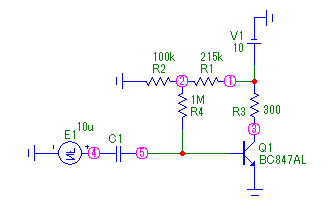
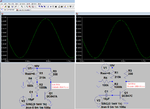
The amplifier has three stages.The input source is photodiode BPW34. i want to calculate gain for individual stages.i don no wat formula should be used.How to calculate...pl sumone help.I attached the circuit diagram.Also wat s te difference of taking output from emitter than collector??
 

Attachments

  • tx_amplifier.pdf
    40.8 KB · Views: 129

Your photodiode is unusually upside down. It is not biased so it is used as a tiny photo cell and produces a small negative voltage when it has light.

Your first transistor is an emitter-follower with a voltage gain of 1.

The second transistor has a voltage gain that is difficult to calculate because the base resistor provides some negative feedback which is reduced by the output impedance of the preceding emitter-follower.
Its voltage gain is somewhere from 80 to 150.

The third transistor has a voltage gain of about 200.

It is much easier to simulate the circuit than to calculate everything.
 

Thanks audio guru for your reply.But as u told gain is 1,i need formula how to calculate it.since photodiode is used it is difficult to simulate.i want to calculate gain theoritically.
 

The first transistor is an emitter-follower (common collector). Look it up in Google.
Its emitter voltage follows its base voltage but is about 0.65VDC less. Its voltage gain is only 1 like a piece of wire.

I do not know if a simulation program has a model for a photodiode so maybe it does not know anything about it.
 

As AudioGuru said, the first stage gain is 1 because it is an emitter follower. The other two stages have very uncontrolled gains because there is no feedback. The gain is highly dependent on the Beta of the transistors. Normally they use an emitter resistor in the common-emitter amplifiers to reduce the gain to a predictable value.

I also question your photodiode connection - especially the fact that DC is blocked. Photodiodes are not bidirectional devices. You should DC couple them to the first stage.
 

The gain is highly dependent on the Beta of the transistors.
No.
The voltage gain of a transistor has nothing to do with its Beta. Beta controls its current gain, not its voltage gain. Voltage gain is simply VRC/VRe where VRe is the transistor's internal emitter resistance.
Without negative feedback, the voltage gain is reduced when the collector resistor has an additional load.

I also question your photodiode connection - especially the fact that DC is blocked. Photodiodes are not bidirectional devices. You should DC couple them to the first stage.
I might agree with you but I have never tried an unbiased photodiode without a DC load. I think the coupling capacitor will become charged by the tiny "solar cell" and stay charged without passing the signal. It will work if the photodiode has a DC load then the coupling capacitor can charge and discharge and pass an AC signal.
 

No.
The voltage gain of a transistor has nothing to do with its Beta. Beta controls its current gain, not its voltage gain. Voltage gain is simply VRC/VRe where VRe is the transistor's internal emitter resistance.

The Q3 stage of this thread's circuit uses just about the worst possible biasing scheme, and Re is highly dependent on Beta; therefore the voltage gain is highly dependent on Beta.
 

Re is highly dependent on Beta; therefore the voltage gain is highly dependent on Beta.
Nope.
Here are two of many articles that do not include beta in the voltage gain formula:
 

Attachments

  • transistor voltage gain.png
    transistor voltage gain.png
    118.8 KB · Views: 98

Is it not true that for the Q3 stage of the OP's circuit (and not some other circuit), the value of Re depends on Beta, since the bias is essentially a fixed current into the base?
 

Nope.
Here are two of many articles that do not include beta in the voltage gain formula:
OK, I see now. But while it is technically correct to say that voltage gain does not depend on Beta, I don't think this voltage gain, as such, is the relevant parameter in assessing the performance of the OP's circuit. Here is why. The output voltage of the Q3 stage is directly proportional to collector current. And Beta is collector current divided by base current. So in this circuit, Beta determines output voltage as a function of base current, while voltage gain is output voltage as a function of base voltage. The distinction between voltage gain and Beta is equivalent to the distinction between base voltage and base voltage. So if we changed transistors to get a higher voltage gain, but kept the same Beta, that could only mean that the new transistor draws more base current for the same base voltage. (I am referring to AC voltages and currents throughout.) That is fine if the circuit driving the amplifier is very low impedance. It would be able to supply the same voltage regardless of how much current is drawn. But in the OP's circuit, the Q3 stage is driven by a stage with an output impedance of 2.7 K and the Q2 stage is driven by 47 K. These driving impedances mean that the base voltage is not independent of the voltage gain of the transistor. In fact it could be more like driving with a constant current than a constant voltage. Therefore current gain, and not voltage gain, is what will determine the final output voltage of the whole 3-transistor circuit for a given signal at the photodiode. And I assume that that is what the OP wants to know the voltage gain for. So I still say that using transistors with a higher Beta is the best way to get the highest signal out of this circuit, even if voltage gain on a stage by stage basis is not as high as it could be.
 

I simulated a transistor with low Beta and one with high Beta. Since the voltage gain is affected by collector current I adjusted the bias so both used the same collector current.
Then the voltage gains ARE THE SAME!

The actual voltage gain is impossible to measure since the distortion is so high because the voltage gain is changing dynamically when the signal current changes.
 

Now try your simulation with a voltage source that has a 2.7 kOhm series impedance instead of zero impedance. That would be closer to the OPs circuit. While you are at it, reduce the signal voltage to get rid of the distortion. (1 mv instead of 25 mv).
 

Of course the distortion is less when the dynamic gain and output current change only a tiny amount.
The fairly low input impedance of the transistor attenuates the signal when there is a 2.7k ohms source resistance.
 

Attachments

  • current gain again.png
    current gain again.png
    49.7 KB · Views: 59

Run the same simulation you did in post #11, but with only 1 mV drive.

Don't include any source impedance, and use different Beta for the two cases as you did in post #11.
 

No, AudioGuru is right that voltage gain is independent of Beta. But the real simulation to try is with the source impedance in both cases, the only difference being the Beta. My contention is that with a source impedance, Beta will affect the output voltage.
 
Last edited:

No, AudioGuru is right that voltage gain is independent of Beta. But the real simulation to try is with the source impedance in both cases, the only difference being the Beta. My contention is that with a source impedance, Beta will affect the output voltage.

It's not always true that the voltage gain is independent of Beta. It depends on the circuit in which the transistor is embedded. The Q3 stage of the circuit from post #1 of this thread is like this:

8742685100_1404592569.png


The base bias is provided through a 1 megohm resistor, which looks essentially like a current source. The base current is nearly constant, regardless of the Beta of the associated transistor, so that the emitter current current depends strongly on Beta. This means that the value of re (the internal emitter resistance) depends strongly on Beta.

The value of Rc (R3 in my image) of 10k ohms is much too high, and the stage is saturated with that value of Rc.

But, if the value of Rc is reduced to something like 300 ohms to avoid saturation, and the input signal is a 1 mV sine wave, the voltage gain of the stage will vary with Beta, because the value of re (the internal emitter resistance) depends on Beta, and the voltage gain is Rc/re.

Normally, one doesn't want the voltage gain to vary with Beta, so biasing schemes are used which cause the emitter current to not vary (much) with Beta. If the emitter current remains constant with Beta, then it's quite true that the voltage gain won't vary with Beta either.

Bypassed emitter resistors are added to a circuit to stabilize the emitter current against variation in Beta, such as in the circuit of Figure 4 on this page:

http://users.tpg.com.au/users/ldbutler/TransisVoltAmp.htm

But that's not the topology of the Q3 stage of the circuit of post #1 of this thread, which is what my post #7 was referring to.

On this page, the author has shown a derivation which apparently shows that the voltage gain of the BJT stage he's discussing doesn't depend on Beta. Look at his equation 5; he assumes that Ie is constant. But in a stage like the Q3 stage of this thread's first post, Ie is not constant. It's value is approximately (β+1)Ib, and Ib is nearly constant because of the 1 megohm resistor. This means that the emitter current is strongly dependent on Beta.

In the circuit of his Figure 4, the bypassed emitter resistor and the low values of R1 and R2 stabilize the emitter current against variations of Beta, unlike the circuit of the Q3 stage of post #1.

In post #7, I said that because of the really bad biasing scheme of the Q3 stage, the voltage gain of that stage is strongly dependent on Beta of the associated transistor. I wasn't commenting on any other circuit, such as the ones that Audioguru has been simulating. If he will simulate the circuit I've shown above, (with only 1 mV drive, because it's the small signal response we're concerned with), and no additional impedance in series with the signal source, the gain will be found to depend strongly on Beta.

So it's not true that the voltage gain of a common emitter BJT stage is always independent of Beta. It depends on the particular circuit used.

Of course, the voltage gain with a source impedance greater than zero ohms will depend on the Beta, because Rpi, the input resistance at the base, depends on Beta, and that input resistance forms a voltage divider with the source resistance. This is not disputed.
 

I simulated the transistor with the 1M bias resistor and differing betas. Different betas caused different operating currents. The different currents caused different voltage gains.
If the operating current is not changed then the voltage gain is not affected by different beta.
 

Attachments

  • transistor with differing betas.png
    transistor with differing betas.png
    51.1 KB · Views: 109

The different currents caused different voltage gains.
If the operating current is not changed then the voltage gain is not affected by different beta.

Indeed. That is just what I explained in detail in post #16. The circuitry in which the transistor is embedded determines whether the emitter current (operating current, in other words) varies with Beta, and that's why the voltage gain may not be independent of Beta.

If the emitter current varies a lot with Beta, then the voltage gain will vary with Beta (in the absence of stabilizing feedback). This is the case with the Q3 stage in the circuit of post #1, and that's what I was referring to in post #7. The bias scheme there is probably the worst thing one could do--use a current source to supply the base bias current. This guarantees that the emitter current (operating current) will vary strongly with Beta. This is not what one should do.

If the circuit is such that the emitter current (operating current) doesn't vary much with Beta, then the voltage gain won't vary much with Beta, assuming the input is driven with a voltage source (zero ohms internal impedance). This is the kind of bias scheme that would be desirable in most cases. Even in this case, the input impedance seen at the base may vary with Beta, leading to a voltage gain that varies with beta IF the source impedance is not zero.

But it's not true to make a blanket, unqualified, statement that voltage gain is independent of Beta; it depends on the circuit.
 

Status
Not open for further replies.

Part and Inventory Search

Welcome to EDABoard.com

Sponsor

Back
Top