Continue to Site

Welcome to EDAboard.com

Welcome to our site! EDAboard.com is an international Electronics Discussion Forum focused on EDA software, circuits, schematics, books, theory, papers, asic, pld, 8051, DSP, Network, RF, Analog Design, PCB, Service Manuals... and a whole lot more! To participate you need to register. Registration is free. Click here to register now.

[SOLVED] how to avoid spikes in the circuit

Status
Not open for further replies.

Aditya070390

Newbie level 6
Joined
Dec 12, 2012
Messages
14
Helped
0
Reputation
0
Reaction score
0
Trophy points
1,281
Activity points
1,384
hi everyone,
i have a circuit to turn on/off a relay depending on two sensor inputs using pic microcontroller,i use a step down transformer to get 12-0-12 output voltage,the problem is ,when i switch on/off the other electrical devices in my home,this relay turns on automatically irrespective of the sensor inputs,help me in providing isolation to my circuit

circuit1.jpg
 

Hello Aditya070390,

do you use shielded cables for the sensor wires? Else, use this.

If this don't help, use opto couplers to isolate the pic controller from sensor lines. Use seperate power supply to bias the sensors and the photo diode.

Regards

Rainer
 

ya am using sheilded cable for the sensors.how can i create another power supply wen i have a single source of power??

y is this circuit affected wen i turn on/off my home appliances??
 

i hav read about MOV's to avoid transients in the circuit.will they solve my problem?? kindly help...
 

Hello Aditya070390,

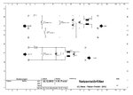
yes, MOV's will avoid transients. Also use a additional filter. Look at the attached circuits.

Netzentstörfilter.JPG

The upper circuit shows you a protection circut to use in Power lines with additional ground connection. The 3 MOV's (VDR1 - VDR 3) protects the circuit against overvoltage between P and N or P and Ground or N and Ground. The rest of the circuit protects against RF trouble. The choke L1 ist a common mode choke.

If you have only P and N use the second circuit.

Take care of the maximum AC - Voltage of the capacitors. It must be higher than you max. line voltage.

**broken link removed**

I use this circuits for all my devices.

I hope this will help you.

Regards

Rainer
 

Related to the suggested usage of Varistors between power lines and protective ground, there's an interesting comment in the Epcos application note:
When varistors are used in line-to-ground circuits, the risk must be considered that a current type fuse may possibly not blow if the grounding resistance is too high and in this way the current is limited. With regard to such cases, various international and local standards do not allow the line-to-ground application of varistors without taking adequate safety countermeasures.

One possible solution is to use thermal fuses in series, which are thermally coupled with the varistor.

In other words, the author is assuming (me too) that the Varistor usage shown in your schematic doesn't comply with safety rules.
 

I think you have to do dome deeper investigation into why the relay is being tripped. I don't believe conducted spikes on the AC input can be the problem, since that should already be significantly suppressed by the transformer, rectifier, capacitors, and regulators together. Have you looked at the behavior of the PIC inputs during these events, as well as the +5V supply voltage, with an oscilloscope? It's possible the the inputs are being triggered, even though the sensors shouldn't be providing the trigger.

edit: it's possible that common mode transients between the sensors and the MCU is causing the I/Os to toggle. If so, using optoisolators instead of BJTs would be a good solution.
 
ya exactly!!! the bc558 caused the transients, i replaced it with bc547 and changed the logic of the program,now its working fine.. thank you all
 

Status
Not open for further replies.

Similar threads

Part and Inventory Search

Welcome to EDABoard.com

Sponsor

Back
Top