Continue to Site

Welcome to EDAboard.com

Welcome to our site! EDAboard.com is an international Electronics Discussion Forum focused on EDA software, circuits, schematics, books, theory, papers, asic, pld, 8051, DSP, Network, RF, Analog Design, PCB, Service Manuals... and a whole lot more! To participate you need to register. Registration is free. Click here to register now.

How to arrest the noise signal in the bridge output during contactor on/off

Status
Not open for further replies.

prakashvenugopal

Advanced Member level 1
Joined
Jun 1, 2011
Messages
473
Helped
15
Reputation
30
Reaction score
15
Trophy points
1,298
Activity points
4,973
Hi all,

I am facing the issue of noise signal comes into my bridge rectifier circuit through transformer 220v.

I am using 220v ac primary --> 22-0-22v secondary. This secondary output is given to bridge rectifier circuit with 2200 uf electrolytic capacitor in the bridge output --> regulator

I am switching ON/OFF the contactor in the same line of transformer 220V ac. Huge noise seen in the bridge rectifier output during contactor ON/OFF. This is reflecting in the regulator output also.

How to solve this noise? Kindly help.

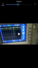
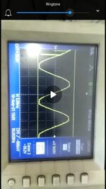
I am attaching the noise signal seen during contactor on/ off in the transformer seconary waveform 0-22v ac measured in oscilloscope and also bridge output signal. Kindly check and please help.

Regards,
V. Prakash
 

Attachments

  • Screenshot_20210814-192500.jpg
    Screenshot_20210814-192500.jpg
    813.1 KB · Views: 164
  • Screenshot_20210814-192538.jpg
    Screenshot_20210814-192538.jpg
    416.2 KB · Views: 164

Solution
Hi,

these signals are fast. Thus you need a fast capacitor.
Often huge capacitors a slow capacitors.

--> thus add a 1uF ceramics in parallel.

But all this does not help if youhave bad wiring / bad layout.

Klaus
"Bridge output" is measured across a big filter capacitor? Then presumedly the signal isn't real but a measurement artefact, common mode noise injected into your single ended oscilloscope probe connection.
 
Hi,

There is an AC at one screenshot. I´m not sure whether this is primary or secondary side.

I agree with FvM. In either case secondary capacitor voltage has to be clean (No other channel should be used to get best results). The noise most probably is an artefact.

Improvements:
Wiring, PCB layout, HF friendly capacitors, filters in general....

Klaus
 
Hi,
Thanks for the reply. Huge capacitor 2200 uf elecrolytic capacitor is used in the bridge output. The regulator voltage is given for amplifier VCC and the amplifier output is given to comparator and is taken out as an output. Whenever i turn contactor ON/off in the same 220v ac supply line, the comparator output changing seems there is a noise in the bridge output and same is reflecting in the regulator output.

Disconnecting the oscilloscope probe gnd and signal wire also, the comparator output is changing. It seems there is no pickup from probe.

When R phase is supplied to transformee primary 220v ac and in Y phase, the contactor is ON/off, there is no problem.

When R phase is supplied for both transformer input and contactor on/off, problem occurs. Problem occurs when using same line for transformer input and contactor ON/OFF. How to solve this noise? Kindly help.

Regards,
V. Prakash
--- Updated ---

Hi,

Image i attached is transformer secondary
Voltage 0-22v ac waveform.

Regards,
V. Prakash
 

Hi,

these signals are fast. Thus you need a fast capacitor.
Often huge capacitors a slow capacitors.

--> thus add a 1uF ceramics in parallel.

But all this does not help if youhave bad wiring / bad layout.

Klaus
 

Solution
Hi,

Thanks for the reply. I already used 0.1 uf ceramic capacitor in parallel with 2200Uf electrolytic capacitor. And also i have tested with two 0.47 uf box capacitor in parallel with them.

Regards,
V. Prakash
--- Updated ---

Hi,

Is this common mode noise? How to arrest the common mode noise. Kindly help?

Regards,
V. Prakash
 
Last edited:

Hi,

if you measure it across a capacitor it surely is not common mode noise.
You don´t see common mode noise across a capacitor.

You can see common mode noise on one capacitor end referenced to EARTH, for example.

It may be an artefact of common mode noise in combination with the scope´s EARTH.

****
Back to your problem.

You need to show a photo of all your wiring: Power input, transformer, rectifier, capacitors, scope connections, scope_mains_connetion...

Klaus
 

Capacitor technologies matter -

1628967023164.png


Short leads matter, no L in them. Look at cap datasheet, one manufacturer to another,
same C, can have significantly different results in package L. In fact you can setup on
benmch a test jig for a cap to see how effective it is.


3 Term Reg protection circuits if reg input << output -

1628969838191.png


A schematic and where you probed might be useful as well.


Regards, Dana.
 
Last edited:

You are effectively making noise with your contactor:
  1. when you turn the contactor off and de-energise the Tx primary - you make a lot of noise - due to energy stored in Imag - lots of volts at turn off.
  2. when you close the contactor there is a pulse of current into the large cap -> NOISE - and the Imag into the Tx may go very high depending on the instant of closure -> NOISE, PLUS the CM effect of energising the Tx primary -> NOISE
Congratulations - you have made a multi-faceted noise generator, both CM & DM.

How often do you turn it ON and OFF ? if once per day not an issue - if for some means of control - time to find a whole new way ....
 

Capacitor technologies matter -

View attachment 171332

Short leads matter, no L in them. Look at cap datasheet, one manufacturer to another,
same C, can have significantly different results in package L. In fact you can setup on
benmch a test jig for a cap to see how effective it is.


3 Term Reg protection circuits if reg input << output -

View attachment 171333


A schematic and where you probed might be useful as well.


Regards, Dana.
Hi,

Thanks for the reply. I am using 2200uf electrolytic capacitor in the bridge output. Can you please recommended what type of capacitor can be added in it to arrest the noise.


I am probing in the V+ IN point of LM 317.in this point only i have 2200uf electrolytic capacitor.

Regards,
V. Prakash
--- Updated ---

You are effectively making noise with your contactor:
  1. when you turn the contactor off and de-energise the Tx primary - you make a lot of noise - due to energy stored in Imag - lots of volts at turn off.
  2. when you close the contactor there is a pulse of current into the large cap -> NOISE - and the Imag into the Tx may go very high depending on the instant of closure -> NOISE, PLUS the CM effect of energising the Tx primary -> NOISE
Congratulations - you have made a multi-faceted noise generator, both CM & DM.

How often do you turn it ON and OFF ? if once per day not an issue - if for some means of control - time to find a whole new way ....
Hi,

I am turning ON/ off the contactor on= 2 sec and off= 2 sec continuously.

Regards,
V. Prakash
 
Last edited:

I suspect a misunderstanding. The SCR suggestion is related to the case, that you want to switch the power to your rectifier circuit. As far as I understand, a contactor in a different circuit is injecting noise.

According to datasheet suggestions, you should have a bypass capacitor directly at the voltage regulator input in addition to the 2200 µF bulk capacitor, e.g. 1 µF. But as already mentioned, it's questionable that you actually have large transients at the voltage regulator input, this could happen if the 2200 µF capacitor is connected through long wires. If not, you see more likely measurement artefacts.

Do you experience actual malfunction of your circuit or is it more a kind of asthetical problem "I don't want to see these spikes"?
 

Hi Fvm,

Thanks for the reply.

Question :As far as I understand, a contactor in a different circuit is injecting noise.
Ans: Absolutely right. Contactors are different thing which we are driving from the same phase. (R phase).


Question:According to datasheet suggestions, you should have a bypass capacitor directly at the voltage regulator input in addition to the 2200 µF bulk capacitor, e.g. 1 µF. But as already mentioned, it's questionable that you actually have large transients at the voltage regulator input, this could happen if the 2200 µF capacitor is connected through long wires. If
not, you see more likely measurement artefacts.
Ans: i am using LM 317 regulator. I have 2200uf electrolytic capacitor and 0.1 uf cap in bridge output. I will try with 1uf electrolytic cap parallel with this. The capacitors are placed closely to the bridge output in the PCB. Not taken any wires.


Question: Do you experience actual malfunction of your circuit or is it more a kind of asthetical problem "I don't want to see these spikes"?

Ans: It is an actual malfunction. Whenever i turned ON/off the contactor in the same line, malfunction occurs. I am not probing any oscilloscope that time. To analyse the malfunction, i am using that oscilloscope.
It is an 100% actual malfunction only.

What are the ways to solve this issue. Kindly suggest?

Regards,
V. Prakash
 

The problem is most likely caused by the succeptibility of the supplied circuit, e.g. microcontroller, discrete logic or analog function. As mentioned previously by KlausST, we need to see the complete setup, also other external connections beside power supply.

General measures to reduce noise injection from power supply are common mode filters, connecting the low voltage ground to earth ground, either directly or by capacitors.
 

Hi,

Thanks for the reply.

Common mode filter in 220V input to transformer primary or 0-22 transformer secondary or in bridge rectifier output?
Kindly suggest.

Question: connecting the low voltage ground to earth ground, either directly or by capacitors.

Ans: what type of capacitors to be used to connect low voltage DC ground to earth ground? Kindly suggest the capacitor type and capacitor value used normally?

Regards,
V. Prakash
 

Hi,

Thanks for the reply.

Sorry for not sharing the image. I am not able to share the image without my organization permission.


Regards,
V. Prakash
 

Status
Not open for further replies.

Part and Inventory Search

Welcome to EDABoard.com

Sponsor

Back
Top