Continue to Site

Welcome to EDAboard.com

Welcome to our site! EDAboard.com is an international Electronics Discussion Forum focused on EDA software, circuits, schematics, books, theory, papers, asic, pld, 8051, DSP, Network, RF, Analog Design, PCB, Service Manuals... and a whole lot more! To participate you need to register. Registration is free. Click here to register now.

How to Add Variable DC Offset to D/A Output

Status
Not open for further replies.

Phosphorous

Newbie level 2
Joined
Sep 29, 2012
Messages
2
Helped
0
Reputation
0
Reaction score
0
Trophy points
1,281
Activity points
1,298
I have a D/A output from an audio card (DAC). The audio signal is AC-coupled so it has no DC component. I need to add a 0-10V variable DC offset, all to be controlled from a computer. This offset will be fairly static. IT will be adjusted to a value and left there for the duration of use or may be adjusted once or twice. I was wondering if this will work...

I plan to use a GE Fanuc (VMIVME-4514A) 16 channel analog output VME board for the 0-10V DC offset.

Will it work if I connect the + of the 0-10VDC signal to the negative of the output of the DAC, and then have the desired resultant signal be seen on the + of the DAC to the (-) of the 4514A?

Will this work or will I need (or want) some other circuitry or diodes for protection? Simplicity is key, cost is not important.

Thanks in advance!
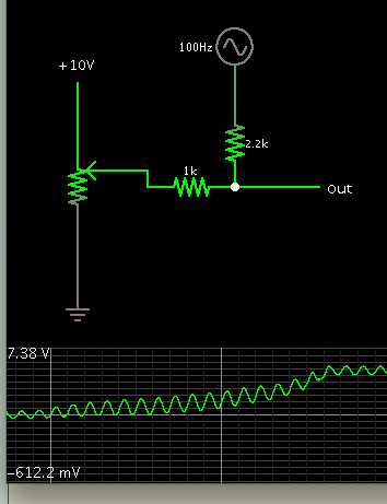
 

This is a typical way to add a DC component to an AC signal.

The potentiometer represents the adjustable DC level coming from your board.

Values are flexible.

The scope trace shows the output as the DC level is varied from lowest to highest.

9002031500_1348904531.png
 

Thank you for your response. One thing I guess I forgot to mention is that I'd like to eliminate any scaling so that if I set the output for an xV offset I get xV instead of a fraction of that. What is the purpose of the resistors in the circuit you provided?

And are you saying that my proposal won't work?
 

Your concept was:

Will it work if I connect the + of the 0-10VDC signal to the negative of the output of the DAC, and then have the desired resultant signal be seen on the + of the DAC to the (-) of the 4514A?

This concept is workable if you were to add a second power supply inline with the power supply that runs the DAC.

It would be fine to do it that way. However it would be cumbersome.

Instead we use resistors and other components in order to level-shift a signal by a certain amount.

Another possibility would be if you could access the DAC internally, so you would set a minimum reference voltage (your 0-10VDC). However this probably is not possible in your soundcard.

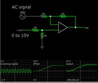
An op amp is the most convenient choice for adding DC to an AC signal without changing its amplitude.

Schematic:


This example has the incoming AC signal at 1V amplitude.
The amplitude is unchanged. Notice the min and max readouts show the outgoing signal is 1 volt above and below the 0-10V range.
 
Status
Not open for further replies.

Part and Inventory Search

Welcome to EDABoard.com

Sponsor

Back
Top