Continue to Site

Welcome to EDAboard.com

Welcome to our site! EDAboard.com is an international Electronics Discussion Forum focused on EDA software, circuits, schematics, books, theory, papers, asic, pld, 8051, DSP, Network, RF, Analog Design, PCB, Service Manuals... and a whole lot more! To participate you need to register. Registration is free. Click here to register now.

how the differential AC signals are produced here?

Status
Not open for further replies.

analog_curious

Member level 2
Joined
Feb 17, 2012
Messages
46
Helped
3
Reputation
6
Reaction score
3
Trophy points
1,288
Location
Ireland
Activity points
1,682
hi all
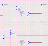
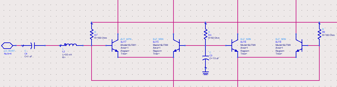
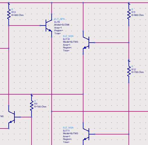
i attach two screenshots of gilbert cell mixer where you can see that that single port is used to supply the differential signal
i also want to confirm my understanding why they have emitter followers at the input to set the DC point for LO stage transistors?
is it because they want to have 50 ohm impedance at the input side?? if not, please help me understand it

also i am not understanding why they need to have 100 ohms for LO+ and 50 ohms for LO-.

thanks all


Dan
 

Which transistors do you consider as "emitter followers"?

also i am not understanding why they need to have 100 ohms for LO+ and 50 ohms for LO-.
If you refer to the bias resistors R3/R7/R9, they are just symmetrical, look sharp. Total impedance is 50 ohm for both ports.
 
he he..sorry..yeah i understand now..was just careless....thanks
emitter followers: yeah in the second attachment(right side figure),the DC points are connected to LO inputs through a buffer (its buffer right or..?) and then a resistor from the supply..Its used for setting the DC points right? or..?

also one more basic question like i asked in my first post...how these signals get differential by supplying a single power source at the LO port..?
is this capacitor at LO(-ve) input is helping to change the phase of the input..? or..
thanks again FvM

(And the inductor and capacitor are not acting as matching networks right..Am it right or..)
I read enough theory about mixers before i start designing but these things confuse me quite much as i have not designed a RF circuit before..


Dan
 

Yes, BJT10 or BJT11 are simply bias voltage buffers, I think. Also BJT9 is apparently a buffer.

Referring to your original question, the single ended input port is fed to a differential pair, presuming the common emitter node is fed by a current source, the output signal will be fairly symmetrical.
 
sorry, but i dont understand your last statement
yes common emitter node is biased by a current source (ok..may be through current mirrors in actual transistor level design) in order to make all the LO stage transistors to be in correct operating region.

but how exactly i get 180 degree phase shifted AC signal at the base of BJT5 and BJT6 for my LO stage ..?
the top level schematic of my attachments just supply a 1tone power source of certain dBm of LO level
I dont understand how my LO stage gets opposite phase inputs for it switch one after the other..?

Dan


thanks for the buffer explanations.I guess they are there to drive low impedance(50 ohms here)
 

Thanks for the info.
Could you please suggest me the possible ways to implement the differential inputs from a single source in terms of MOSFET based gilbert cell.


Dan
 

An ideal differential amplifier (infinite output impedance of involved transistors) is only sensitive to differential input voltage, so there's no problem to drive it single ended. This is valid for BJT and MOSFET as well.

In a real circuit, transistor output impedances as well as capacitances cause a certain common mode sensitivity. In practice, you should determine the performance of your multiplier circuit for single ended operation compared to differential and decide if it's acceptable or you better should place a balun or balancing amplifier in front of it.
 

Status
Not open for further replies.

Part and Inventory Search

Welcome to EDABoard.com

Sponsor

Back
Top