Continue to Site

Welcome to EDAboard.com

Welcome to our site! EDAboard.com is an international Electronics Discussion Forum focused on EDA software, circuits, schematics, books, theory, papers, asic, pld, 8051, DSP, Network, RF, Analog Design, PCB, Service Manuals... and a whole lot more! To participate you need to register. Registration is free. Click here to register now.

[SOLVED] How many LEDS Off a 555

Status
Not open for further replies.
Get a calculator, spend an hour getting it wrong until something seems right, and confuse yourself even more like I have to do, then ask the question, my friend :)

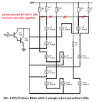
See what a 900 Ohm in parallel with a 580 becomes.

That's not the point anyway, maybe I'm wrong but I understand that the 180R will stay 180R (it's a series resistor), it limits the same amount of current to n number of parallel strings, whether that's 1 in series or 5 in parallel.

I'm saying this with a smile on my face, "You're still simulating this, having the LEDs and devices there in your hands, aren't you?" Get away from the computer and watch a few LEDs pass from the right colour to a brief worrisome orange then red then burnt out in a split second, it's fun. Experiment, if you aren't already.
 

A higher value for a current-limiting resistor that feeds LEDs REDUCES the current so you cannot add (series) the values, they are in parallel. You should not think about how many LEDs you have, you should think that you have 6 strings of LEDs including the one string with a resistor replacing one LED.
I do not know why the WIZARD wrongly shows 180 ohms for each string (8.9mA) instead of 160 ohms (exactly 10mA). 160 ohms is a standard 5% resistor value.

-Your 555 IC is not powered because you have the supply bypass capacitors in series with the positive supply instead of as a bypass from the positive supply pin 8 to ground pin 1.
-The CD4017 IC is not powered with +9V and 0V.
-You still show the symbol of an ordinary transistor that will not work in your circuit instead of the symbol for a darlington.
-The value you have for R4 is fine for limiting the current (12.3mA) for only 2 LEDs in series but will cause the 6 strings of LEDs to each have very low current and be very dim.
-The value you have for R5 will limit the current of its LED to only (3.2V/580 ohms=) 5.5mA. Also 580 ohms is not a standard resistor value.

- - - Updated - - -

....watch a few LEDs pass from the right colour to a brief worrisome orange then red then burnt out in a split second, it's fun.
I saw my first LED in 1964 and wrongly thought its junction was red hot. But it felt cold.
Since then I have used thousands of LEDs and NEVER had one burn out because I learned that they must have their current to be limited as shown on their datasheets. NONE of the thousands of transistors I have used also NEVER burned out.
Some of my LEDs and transistors got fairly warm.
 

Last year I put a 5mm green LED on a 9V battery to see what would happen with no resistor, it was a deliberate action (unlike the few components I have in the "Oops" bin I keep to remind myself to be cautious). As you say:

...they must have their current to be limited as shown on their datasheets.
 

I was trying to use a calculator hence why im struggling with it all.

Oh no ive been experimenting with a breadboard and components to see what they all do, a few dead LEDS a few burnt finger tips, thinking ouch how did that small little LM35 become so god dam hot :).


I cant find a symbol for a Darlington (Transitor) in the software

Its working now after I changed the values of the resistors but I need to put the caps in the right place.

caps.png


There is no pin for +9v and 0v on the CD4017 in proteus, it just works.
 
Last edited:

Well I think I have done quite well since my first post.

9V Supply

Resistor Calculations:
8 - 6.4 (2x3.2 VD) / 0.02 = 80 (Closest Highest Value) 82 OHM for 2 Strings of LEDS
8 - 3.2 / 0.02 = 240 (Closet Highest Value 270 OHM) 1 LED


I have decided to have one resistor for each string of LEDS.

I have added 2 LEDS above 2 letters this is for me to understand :).

I have figured out the BC517

I have bypass caps, apart from the 4017 because it doesn't show the +/- on the software.

One thing I would like is it to flash EURO (All 4 letters at the same time) then TECK (All 4 letters at the same time).

I don't know how to skip an out put like skipping Q2 - Q8

Im happy for sure, the teck is missing.

PDF Attached

- - - Updated - - -

Actually,

Resistor Calculations:
8 - 6.4 (2x3.2 VD) / 0.02/ 2 = 40 (Closest Highest Value) 47 OHM for 2 Strings of LEDS
8 - 3.2 / 0.02 = 240 (Closet Highest Value 270 OHM) 1 LED


- - - Updated - - -

Actually the first Calc is for resistors in series and the second is for resistors in para.

- - - Updated - - -
 

Attachments

  • eur01.pdf
    140.4 KB · Views: 76
Last edited:

- - - Updated - - -

On your first letter you have the 47 ohm resistors and the series pairs of LEDs shorted all together.
The current in the LEDs is too high.
The current in the single LED is different.

A CD4017 turn on only one output at a time so only one letter lights at a time.
To flash a few letters then flash a few more letters then replace the CD4017 with a flip-flop IC.
 

Attachments

  • first letter.png
    first letter.png
    27.4 KB · Views: 74

Ive update the PDF since then :).

Ah i have a flip flop :).

just need to know how to wire up :)
 

If you have a CD4013 dual flip-flop IC then you use one flip-flop and disable the unused one by connecting its four inputs to 0V.
Connect the Q output to the series base resistor of the darlington that feeds the first word and connect the Q-not output to the second darlington. Connect the Q-not output to the D input.
Then for each clock pulse its outputs toggle: EURO, TECH, EURO, TECH etc.
I did not calculate how hot both BC517 darlingtons will get. Since their current is much higher then the value of their base resistors must be reduced. If the base current is too high for the CD4013 to drive then replace the darlingtons with logic-level Mosfets.
 
  • Like
Reactions: d123

    d123

    Points: 2
    Helpful Answer Positive Rating
Ive just remembered, I did this for my course.

Okay ill see how it all goes, hoping to get a Letter or Two built up today.

Im going to took into the transistor Calculations.

I can see what you mean by the BC517 might get hot, I have increased each LED to be 20mA, so the total current drawn from the trans needs to be 0.24mA but the output of the BC517 fully saturated is 1A

- - - Updated - - -

Or is Saturated like a Dam and the current comes like a Tilde Wave

- - - Updated - - -

Sorted :).

FLASHED EU THEN RO.

All I want to do now is make sure I have the Transistor setup correct
 

Attachments

  • euro flip flop.pdf
    114.5 KB · Views: 85
Last edited:

Your schematic drawing software does not know that ALL Cmos logic inputs MUST be connected to logic high or logic low. The Set and Reset inputs of a CD4013 must be connected to 0V in your circuit or it will not work! The CD4013 also must be powered and have its other flip-flop properly disabled with its all four inputs connected to 0V.

Why do you have a BC517 darlington for each letter? Each letter draws about 120mA so four letters will draw 480mA. The darlington has a saturation voltage loss of 1V so its heating will be 480mW. Its thermal resistance from junction to ambient is 200 degrees C per W so its internal temperature will be (480mW x 200 degrees) plus the ambient which might be 30 degrees= 126 degrees C which is less than its max allowed temperature of 150 degrees C. The darlingtons alternate on and off so their average temperatures will be much less. Since their collector current is 4 times higher than one letter then their base resistor values should be reduced to 15k ohms and the CD4013 will have no trouble driving them.
BUT DO NOT DO THIS because Philips and maybe other manufacturers rate their BC517 at only 500mA, 0.5W and 250 degrees C per W. Fairchild and Motorola/ON Semi rate theirs at 1A, 1.5W and 200 degrees C per W.
 

Now im upset :-(.

Yes, i know about the high and low but i cant show that in the Sche, for some reason

I assumed that was correct as ive done the same since the start and no-one has commented.

Or is this because i have changed the IC?

So i only need 1 bc517 for 4 letters with a 68K resistor? Technical Stuff
 

Ah i see what you mean!.

The CD4013 is now triggering 2 letters all at once.

so pulling double the amount of current, i thought if it pulled 120mA for each letter for each BC517 the transistor will be better off.

THE DARLINTON TRANSISTORS ARE NOT CORRECT :-(, thats causing my confusion.
 
Last edited:

I do not know why your schematic drawing software will not allow you to connect the CD4013 Set and Reset pins to 0V which is also the ground on the circuit.
As I said, each manufacturer of a BC517 has different maximum ratings so it is best to use one BC517 with a 68k series base resistor to drive each letter with 120mA.
 
Ive done that now :).

I though you said not to have one BC517 for each letter!!

So for 8 letters ill use 8 BC517 and not 2
 

Attachments

  • euro flip flop.pdf
    114.5 KB · Views: 80
Last edited:

I saw Fairchild's datasheet for the BC517 before I saw the datasheet from Philips. I expected them to have the same ratings but they don't. Since you will test using a solderless breadboard then a BC517 driving only one letter is best since the spec from Philips says its maximum allowed heating when it is soldered to a pcb that has lots of copper. The pins feed the heat to the copper.
 

Wow, you do know your stuff :).

I really do appriciate your replies, you are making me understand my electronics much more.

Ive started to bulid on breadboard 555 timer is done.

Next the FLIP FLOP

- - - Updated - - -

I dont have a 4013 which i though i did.

i have a 7474, i new a had one type opps SORRY. Seems to be no difference in the two works on the software

- - - Updated - - -

I have a logic probe :)
 
Last edited:

Hi there! Hope it's going well, Englewood. Just trying to add even more confusion to the thread, you seem to be doing too well ;).

I haven't thought about it much, needs a lot of re-work/ironing out, as you'll see, and I've avoided the subject of resistors and especially where they should go (!). The schematic uses 2 4017s to write E-EU-EUR-EURO-EURO-T-TE-TEC-TECH-TECH-EUROTECH.
Had meant it to write E-U-R-O-EURO-T-E-C-H-TECH-EUROTECH, (that explains the odd repetition of EURO and TECH!) then realised I'm not sure how the diodes would need to go for that, I'm tired so this is my best offering in that respect for now. Anyway, it's easy to do, something to think about if you want.

Hope you're fine!

View attachment LED letter circuit - Schematic.pdf


...one of the downsides to this circuit which is obvious is that the voltage drop from so many diodes in series would be unfeasible on 9V... It is possible to fan out the "outputs" (they are outputs, and when I understand real flow of electrons - not textbook - and how NPNs work, I'll figure out why I put that in inverted commas) of transistors #5 and #10 into 4 separate lines going where they have to go respectively so the voltage drop is only about 0.7V on each line.
I read somewhere that paralleling diodes is like paralleling resistors, not sure what that meant though, apart from the person saying it reduces the voltage drop, I have no idea if that is correct.
Transistor #11 would be a problem to do the above with, 10 diodes and the respective cables...
I think my torch has about 40 diodes on it, and operates on 12V... Was it worth it? Probably, but anyway.

Some-one more used to diode "mazes" will be able to correct the mistakes.

- - - Updated - - -

Very quickly, just remembered, the schematic has a big mistake in it, if ever use 2 4017 for this type of circuit, the second one would need first output left floating (or tied to ground with a resistor but that is totally unnecessary, only CMOS inputs need to be tied to an appropriate logic level, as Audioguru already said).

i.e. 4017 #2 should be pin 3 left floating, pin 2 to transistor #11, pin 4 tied to reset pin 15. All assuming a power-up reset is used.

Sorry about that mistake in the picture.
 
Last edited:

You don't say - I hadn't noticed ;). It was just a suggestion as it had been mentioned earlier a few posts back, not a recommendation to change the ...7474.
 

Haha, sorry i though you missed that part.

Well im trying to work out the 7474 on breadboard or i might pop to the electronics store and get a 4013 in the morning, as its raining cats and dogs tomorrow :-(.

Your confusing me even more with your diodes ha, i have a lot to learn for sure :).
 

Status
Not open for further replies.

Part and Inventory Search

Welcome to EDABoard.com

Sponsor

Back
Top