Continue to Site

Welcome to EDAboard.com

Welcome to our site! EDAboard.com is an international Electronics Discussion Forum focused on EDA software, circuits, schematics, books, theory, papers, asic, pld, 8051, DSP, Network, RF, Analog Design, PCB, Service Manuals... and a whole lot more! To participate you need to register. Registration is free. Click here to register now.

[SOLVED] How many LEDS Off a 555

Status
Not open for further replies.

Englewood

Full Member level 3
Joined
Nov 2, 2014
Messages
178
Helped
0
Reputation
0
Reaction score
0
Trophy points
16
Activity points
1,294
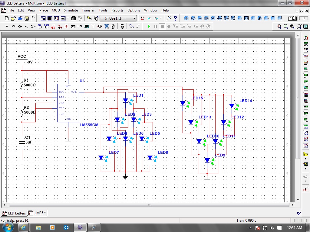
I want to make a running light of LEDS though a NAME.

Lets say ENGLEWOOD

Each letter will take 10 LEDS make and i want each letter to flash in a running sequence.

Is it possible to run a 90 LEDS off 1 555 timer?

Or will i need a timer for each letter?

Will this run off a 5v supply or would i need 9V.

90 x 20ma 1800ma for the current for LEDS.

I will run the LEDS in parallel
 

Are the letters fixed or are you using a graphic matrix? If the first and you just wish to change the current letter to other, yes a 555 coupled with a 4017 could certainly be used.

This will run from wathever supply you want. How much current is the issue. For 10 leds 10-20mA per led is 100-200mA total times whatever characters you have. I would advise you to wire them up in series and power them from a 20-30V output. This would be the most efficienct way, power wise. If pluggued in parallel then the higher the voltage the more power wasted on the limiting resistor (current would be the same).
 
Last edited:

fixed or matrix? sorry ima NEWBIE

I want each letter to light up for second or two then on to the next letter.
 

Fixed as you have 10 leds making the letter A and you only need to supply power or matrix in wish you have row and collumn and you power the necessary leds to make whatever letter you want, such as in a display.

Assuming the first (you power a fixed letter each time) then a 555 clocking a 4017 would suffice.
 

Yes thats correct.

Each letter will be about 10 LEDS, one will be 7.

Will i need a 555 timer for each letter? or use a 4017.

Ive used decade counter before
 

I've built these before with a SChmitt Trigger Osc and Pot for variable speed> CD4017> then NPN driver

Choose each string to add up to just below Vcc i.e. 12V and allow 1~2V for small R series current limiter then make parallel array depending on colour 3V for White, 2V for Red/Yel. This is works.

First define what LEDs are used and what power is avail.

If you choose White, and low Vce(sat) or FET you can use 4S3P array drawing 80mA with 12 LEDs per Letter with 0 Ohm on 12V
 

Okay ive had a little play today just running about 20 LEDS off a 555 timer.

I made 2 letters one with WHITE LEDS and 1 with BlUE LEDS and worked fine both letters flashed.

Then i went to make 2 letters one with RED LEDS and one with BLUE LEDS but for some reason the BLUE and RED wouldnt work together.

The BLUE and WHITE worked together but the RED and WHITE wouldnt is this to do with there FV??
 

How can we explain how to fix your circuit without seeing its schematic?
We do not know if the LEDs are in series or parallel and we do not know the supply voltage.
We also do not know what circuit the 555 is in, mono or astable?
How many 555 ICs did you use? Did you use any transistors?
 

The blue and white have a forward voltage of 3V, while the red/green/yellow have a forward voltage of only 2V. So you need to make sure you have enough voltage plus a overhead for the resistor to keep the current constant, otherwise the red ones will drop the voltage to a value too low for conduction of the white/blue. A schematic would be helpfull to calculate circuit parameters.

You only need one 555 timer. Configure it for a 0.1Hz square wave and feed that into the decade counter.
 

How can we explain how to fix your circuit without seeing its schematic?
We do not know if the LEDs are in series or parallel and we do not know the supply voltage.
We also do not know what circuit the 555 is in, mono or astable?
How many 555 ICs did you use? Did you use any transistors?

Sorry im new to this as you can tell :).

555 timer is in astable and ive only used one. No transistors.

9V supply.

Ill try and do a schematic
 

I havent been using a Schematic, i just had the parts and had a play.

Here is one Schematic of one circuit i made and is working with BLUE/WHITE LEDS.

But dosnt work with BLUE/RED LEDS

The schematic is of BLUE & GREEN LEDS as they dont do white :-( ha.
 

The output of the 555 is trying to go up to about 7V but your LEDs are shorting the output of the 555 to the forward voltage of the LEDs (2V or 3V).
1) LEDs need to have a series resistor to limit the current.
2) Each LED has a slightly different forward voltage so they should never be connected directly in parallel like you show.
3) The datasheet of the 555 shows that its maximum allowed output current is 200mA and if your power supply can supply a lot of current then your 555 and LEDs would have gotten so hot that they would have failed.
If you connect a 3V blue LED parallel with a 2V red LED then the blue LED does not get 3V so it will not light. If each has a series resistor to limit their current then both will light.

You can connect two white or blue LEDs in series and in series with a current-limiting resistor. Since you have 20 LEDs and 200mA max then the current in each LED must not be more than 10mA.
You can connect three red LEDs in series and in series with a current-limiting resistor. The output of the 555 will safely go up to 7V and light all the LEDs.
The current-limiting resistor value is calculated using Ohm's Law (the voltage across the resistor divided by the current in it).
 
  • Like
Reactions: d123

    d123

    Points: 2
    Helpful Answer Positive Rating
Thank you for your reply.

I can understand most of what you have said there.

I have made the circuit on a breadboard and its working fine with no overheating no fried LEDS.
Ive had it running all night with out a problem.

The only difference is that i have a 470 OHM Resistor going from the output pin of the 555 timer to the 1st LED
 

As above, completely.

I learnt that strings of LEDs go in parallel groups of no more than 3 (sum the voltage drops to know the limit your supply/output can provide for), which has nothing to do with the pattern.

You can squeeze a lot out of appropriate parallel strings, e.g. @ 12V, 7 parallel rows of 3 = 21 x 10mm white or blue LEDS.

The resistors are really important.


Hope it goes well!
 

I am wasting my time talking to you since your schematic did not show the extremely important 470 ohm resistor.

The LEDs are in parallel then the 470 ohm resistor from the output of the 555 to the first LED also connects to all of the LEDs.
Simply use Ohm's Law to calculate the output current from the 555:
1) The output of the 555 will go up to about 7V when it has a 9V supply.
2) White and blue LEDs have a forward voltage of about 3V.
3) Then the 470 ohm resistor has a voltage of 7V - 3V= 4V across it and Ohm's law calculates the total output current to be 4V/470 ohms= 8.5mA. Since the current is so low then the graph in the datasheet shows a loss of only 1.4V instead of 2V so the output with a 9.0V supply will go as high as about 7.6V and the total output current will be 9.8mA. A 555 is able to have an output current as high as 200mA.

Your schematic shows 15 LEDs in parallel. If they all have the same forward voltage then each one has 9.8mA/15= 0.65mA which will be VERY dim. Ordinary LEDs are rated with 20mA.

Yes im very sorry about that, it was very late last nght when i was doing the Schematic.

My output of the 555 timer is 6V.

My LEDs are bright enough i guess but running another 80 LEDS im not going to see nothing.

Rethink then.

Your replies have been very helpful, this is all new to me and im on a very steep learning curve by the looks of it
 
Last edited:

If the output of your 555 is only 6V and the load is only about (6V - 3V)/470 ohms= 6.4mA then the datasheet graph shows a supply that is 7.4V which is a pretty dead 9V alkaline battery or an old Ni-Cad one.

If you use a 12VDC power supply instead then the LEDs can be in series strings and each string can have its own series current-limiting resistor. You can connect two 3V LEDs in series or three 2V red LEDs. 90 LEDs will make about 36 strings and the total current will be only 23mA. The output of the 555 will be about 10.6V. Since the current of only 0.65mA is bright enough then the current-limiting resistor for each string of 3V LEDs is (10.6V - 6V)/0.65mA= about 6.8k ohms. The series resistor for each string of 2V LEDs is (10.6V - 6V)/0.65mA= also about 6.8k ohms.

The LEDs will be much brighter if their total current is increased to 150mA, then the current in each string is 150mA/36= 4.2mA. At 150mA, the output of the 555 will be about 10.3V so the resistors for each string of LEDs is (10.3V - 6V)/4.2mA= about 1k ohms.
 

An astable 555 timer sending clock pulses to a 4017 counter. The counter outputs go into NPN transistors powerful enough to supply the current for the 7 - 10 LEDs of each letter. Calculate the current you need for 2 or 3 LEDS in series, size each resistor accordingly, and spread those 7 - 10 in little parallel groups. Any transistor that can comfortably supply at least 100mA (10mA) per LED without getting hot will do.

Things like emergency service sweeping lights function on a similar principle. I think it's called "555 timer circuits. com" has a motorbike sweeping LED indicators circuit using the 4017 and diodes.

OR a good way of using a lot of diodes is to use not 90, but just enough LEDS to make the equivalent of a 14-segment display, and configure the transistor outputs to create each letter with endless diodes preventing the output from each successive stage going into the output of the previous one - this method takes a long time to wire and place the diodes strategically.

Anyway, the counter/divider driven by the 555 will spell O H M S L A W A N D S E R I E S A N D P A R A L L E L R U L E S AP P L Y I N E V E R Y C I R C U I T, or E N G L E W O O D, or whatever you want.

Englewood is 9 letters, the 4017 has 10 outputs - with a clock pulse it's a really typical way of flashing with an analog device. Good luck.
 

The OUTPUT of my Power source is 240v down to 9.06V, its mains not a battery.

When i measured the output of the 555 timer it was 6.08V

The voltage drop across the 470 is 3.45V

You guys are very clever, ive got years of electronics ahead of me by the looks of it.
 

Status
Not open for further replies.

Part and Inventory Search

Welcome to EDABoard.com

Sponsor

Back
Top