Continue to Site

Welcome to EDAboard.com

Welcome to our site! EDAboard.com is an international Electronics Discussion Forum focused on EDA software, circuits, schematics, books, theory, papers, asic, pld, 8051, DSP, Network, RF, Analog Design, PCB, Service Manuals... and a whole lot more! To participate you need to register. Registration is free. Click here to register now.

How is it possible for nMOS threshold voltage to become negative?

Status
Not open for further replies.

anhnha

Full Member level 6
Joined
Mar 8, 2012
Messages
322
Helped
4
Reputation
8
Reaction score
4
Trophy points
1,298
Activity points
3,684
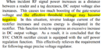
I am reading about self-Vth-cancellation in CMOS rectifier circuit and the yellow text below makes me confused.
How is it possible for nMOS threshold voltage to become negative?
Hope someone help me out. Thank you.

Self-Vth-cancellation CMOS rectifier.PNG

broken link removed
 

Attachments

  • Self-Vth-cancellation CMOS rectifier 1.PNG
    Self-Vth-cancellation CMOS rectifier 1.PNG
    112.5 KB · Views: 264
Last edited by a moderator:

The term "effective threshold voltage" has been created by the author to explain the operation of the circuit. Actual threshold voltage doesn't change.

A (more?) simple explanation is that with DCout above Vth both MOSFETs start to conduct simultaneously.
 

I think the author actually meant to say the threshold voltage can be negative.
From the same article:

In this case, energy loss in the rectifier circuit is caused only by a resistive loss at forward bias condition. Therefore, PCE is almost determined by an effective on resistance of the diode-connected MOS transistor. The lower the threshold voltage of the MOS transistor is, the lower the effective on-resistance becomes. Therefore the large PCE is obtained if threshold voltage can be minimized.
However, when the threshold voltage of MOS transistor is too small so as to become negative, reverse leakage current cannot be ignored. If noticeable reverse current exists, it directly results in the energy loss since charges flowing in a reverse direction is just simply wasted.

https://ieeexplore.ieee.org/stamp/stamp.jsp?tp=&arnumber=4425746
 

You can build "zero-VT" FETs and this is very common in RF
processes. The "native" FETs have a target of zero-ish and
a process control range which straddles both sides of zero.

N+ poly over a N- body with N+ S/D makes a true depletion
mode FET (provided that the N- is thin enough, else you
will not have gate authority over all of the conduction
path. In thin SOI this is doable and I've used these devices
for special purposes (despite rather lousy control range
and some trouble standing off drain voltage at short channel).

"Effective" anything usually means the author doesn't
know what the "real" deal is. Subthreshold leakage (really
conduction) is the more likely actor. But digital folks doing
low power RF don't want to hear from device physics.
 

Hi, I know that we have zero VT in native mosfets. However, as from my post #3, I think that the author really meant to say that the threshold voltage can be reduced to negative value.

In this case, energy loss in the rectifier circuit is caused only by a resistive loss at forward bias condition. Therefore, PCE is almost determined by an effective on resistance of the diode-connected MOS transistor. The lower the threshold voltage of the MOS transistor is, the lower the effective on-resistance becomes. Therefore the large PCE is obtained if threshold voltage can be minimized.
However, when the threshold voltage of MOS transistor is too small so as to become negative, reverse leakage current cannot be ignored. If noticeable reverse current exists, it directly results in the energy loss since charges flowing in a reverse direction is just simply wasted.
 

Status
Not open for further replies.

Part and Inventory Search

Welcome to EDABoard.com

Sponsor

Back
Top