Continue to Site

Welcome to EDAboard.com

Welcome to our site! EDAboard.com is an international Electronics Discussion Forum focused on EDA software, circuits, schematics, books, theory, papers, asic, pld, 8051, DSP, Network, RF, Analog Design, PCB, Service Manuals... and a whole lot more! To participate you need to register. Registration is free. Click here to register now.

How does this circuit work?

Status
Not open for further replies.

an_82

Member level 2
Joined
Oct 6, 2013
Messages
52
Helped
7
Reputation
14
Reaction score
7
Trophy points
8
Location
Delft, Netherlands
Activity points
303
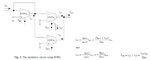
I studied a paper attached with this post . I have a question about Fig. 3 which is also attached where a topology to realize multiplier circuit has been presented:

How can we apply "iin1" to "EOTA1"? In the paper it is mentioned that "gmT1" has a direct proportion to "IBE1", when we change "IBE1", "io1" changes and since "iin1= io1", "iin1" changes. If we apply "iin1" ideally, it seems that "io1" cannot change. Could you please explain how we apply input signal and how does it work with these conditions ? (I know all of the formulas, please explain applying of signals)

Thanks.
 

Attachments

  • mull.jpg
    mull.jpg
    43 KB · Views: 134
  • OTA Divider.pdf
    553.4 KB · Views: 101

an_82,

you have nothing to do than to combine the established OTA formulas in a correct way using

Un; Up: OTA input voltages at the negative resp. pos. input terminal
g1 ; g2 : OTA transconductances
Iabc=Control current into the external control node for determination of g (abc: amplifier bias current), in your case: Iabc=Ibe1 and Iabc=Ibe2+Iin2

Start with (I am using capital letters for better reading):

Io1=-Iin1
Io1=-Un1*g1
Un1=Up2
Io2=Up2*g2

This results in Io2=Iin1*g2/g1

With g=Iabc/(2*Uth) you arrive at the given expression for Io2.
It is easy to find Io3 in the same way.
 

Dear LvW,

Thanks for your reply, but as I said I know all of the expressions. I mean that how can I simulate the circuit (in Hspice)? I putted CMOS transistor level of OTAs, then if I apply iin1 ideally, since iin1= -io1, io1 should be equal to applied iin1, while it can be changed by its "Iabc" !! how can I apply iin1 in the case that when I change "Iabc1", its "gm1" and consequently "io1" be change?
 

Thanks for your reply, but as I said I know all of the expressions. I mean that how can I simulate the circuit (in Hspice)? I putted CMOS transistor level of OTAs, then if I apply iin1 ideally, since iin1= -io1, io1 should be equal to applied iin1, while it can be changed by its "Iabc" !! how can I apply iin1 in the case that when I change "Iabc1", its "gm1" and consequently "io1" be change?

You are asking "how can I apply iin1"?
My answer: As a current source. Or did I misunderstand something?
Perhaps it helps, as a first step to simulate the circuit using IDEAL OTA blocks (VCCS) with varying gm values.
Real OTA`s have a separate pin to inject Iabc.
 

Status
Not open for further replies.

Similar threads

Part and Inventory Search

Welcome to EDABoard.com

Sponsor

Back
Top