Kelly01
Newbie
MEMS gyroscope continue to face challenges as an emerging device. Nowadays, more and more application fields require gyroscopes to collect receipts in high-temperature environments. Compared with other types of gyroscopes, MEMS gyroscopes are smaller, have lower cost and power consumption, and can be used on semiconductors of the same size. The signal conditioning circuit is integrated into the package and is more flexible. However, continuous operation in a harsh and high-temperature environment may cause the equipment to be continuously affected by shock and vibration, resulting in failure or excessive wear. Moreover, the temperature of most MEMS gyroscope is between -45℃ and +85℃, which obviously does not meet the requirements of high-temperature environments. Therefore, in order to meet market demand, Ericco developed and produced the high-temperature north-seeking MEMS gyroscope ER-MG2-022 that can adapt to harsh high-temperature environments. It can accurately measure angular rate in the face of shock and vibration, and its maximum working temperature can reach 125℃.
The following will introduce the working principle, vibration suppression, installation and application of MEMS gyroscopes.
The working principle of MEMS gyroscope
MEMS gyroscopes are based on the Coriolis force and use Coriolis acceleration to measure angular rate. Figure 1 explains the Coriolis effect. The blue circle in the picture is the rotating platform. We imagine that we are standing near the center of the rotating platform. Our speed relative to the ground is represented by the length of the blue arrow. If we move to the outer edge of the rotating platform, our speed relative to the ground will increase in speed, represented by the longer blue arrow. The growth rate of tangential velocity caused by radial velocity is Coriolis acceleration. To put it more simply, when we move from the center of the rotating platform to the outer edge, we need to increase the velocity component to maintain our moving path. The acceleration required in this process is Coriolis acceleration.
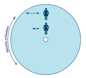
Figure 1. The example of Coriolis Acceleration
Figure 2 illustrates the Coriolis effect. When the resonant mass moves toward the outer edge of the rotating platform, it accelerates to the right and exerts a reaction force to the left. As it moves toward the center of rotation, it exerts a force to the right (green arrow in the figure).
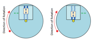
Figure 2. Coriolis effect
Coriolis acceleration is measured using a spring at 90° to the direction of motion, with the frame containing the resonant mass attached to the substrate (Figure 3). Figure 4 shows its complete structure. When the mass body moves and the installation body where the gyroscope is located rotates, the mass body and its frame will be affected by Coriolis acceleration and rotate 90° due to vibration.
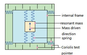
Figure 3. Gyroscope mechanical architecture principle
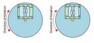
Figure 4. Frames and masses are affected by the Coriolis effect
Vibration suppression of MEMS gyroscope
The gyroscope is only sensitive to rotational speed and is insensitive to other things. This is an ideal situation. However, in actual situations, due to the asymmetric mechanical design of the gyroscope and the possible insufficient accuracy of micro-machining, the gyroscope will have a certain sensitivity to acceleration. Acceleration sensitivity takes many forms, and its severity varies depending on the design. The most serious ones are the sensitivity to linear acceleration (g sensitivity) and the sensitivity to vibration rectification (g2 sensitivity). According to our experimental data, the g value sensitivity of ER-MG2-022 <1 °/hr/g, and its vibration correction error (12gRMS, 20-2000) <1 °/hr/g (rms), shock (charged) is 200g (1ms, 1/2 sine), shock resistance (uncharged) is 1.8wg 3ms, vibration (charged) is 12g rms (20Hz to 2kHz). This shows that Ericco’s high-temperature north-seeking MEMS gyro has excellent performance and can withstand harsh environments and strong impacts.
Installation of MEMS gyroscope
The resonator circuit detects the velocity of the resonant mass, amplifies it and drives the resonator while maintaining a well-controlled phase with respect to the Coriolis signal path. The Coriolis circuit is used to detect the movement of the accelerometer frame, using downstream signal processing to extract the magnitude of Coriolis acceleration and generate an output signal consistent with the input rotational speed. In addition, the self-test function also checks the integrity of the entire signal chain. Figure 5 shows the schematic diagram of the integrated gyroscope.
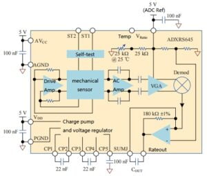
Figure 5. Schematic diagram of an integrated gyroscope
Application scenarios
Take the oil and gas downhole drilling fields as an example, because the working environment in this industry is the most demanding for electronic equipment. In this field, its equipment systems use sensors to better understand the operation of the drill string below the surface to optimize operations and prevent damage. RPM is the unit used by drilling rigs to measure rotational speed and is a key indicator that drill rig operators need to master. Previously, this indicator was calculated by a magnetometer, but the magnetometer is easily affected by iron materials such as drilling rig casing and wellbore.
At the same time, understanding the movement of the drill string and the dynamics of the drill string have also become important data, so that parameters such as the magnitude of the applied force, rotation speed and steering can be better managed. Drill string dynamics, if not managed properly, can result in highly vibrating and erratic movement of the drill string, which can result in extended drilling times in target areas, premature equipment failure, difficulty in turning the drill bit, or damage to the well. There are even some extreme situations where equipment breaks or remains in the drilling well, and it is very costly to retrieve the equipment.
Poor management of drill string parameters can lead to a type of movement that is particularly harmful called stick-slip. The specific explanation for stick-slip is that the drill bit gets stuck, but the top of the drill string continues to rotate. After the drill bit is stuck, the bottom of the drill string continues to rotate and tighten. When sufficient torque is reached, it will cause breakage and loosening. This breakage is usually very violent. Stick-slip generally occurs periodically and can last for a long period of time. A cross-sectional view of the stick-slip cycle RPM can be seen in Figure 6 . Stick-slip occurs, but the drill string on the surface continues to operate normally, and the rig operator is often unaware of what is actually happening downhole.
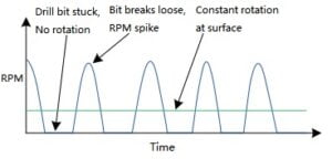
Figure 6. Profile of stick-slip cycle RPM
In this application scenario, the key to the measurement method is to accurately and frequently measure the rotational speed near the drill bit. Gyroscopes are well suited for this task because their measurements are not affected by linear movement of the drill string. When high vibrations and unstable movements occur, the rotational speed calculated by the magnetometer is susceptible to noise and errors, while the gyroscope can quickly derive the rotational speed and is less susceptible to shock and vibration.
What’s more, gyroscope-based circuits are smaller and require fewer components, making them simpler than magnetometer-based solutions. ER-MG2-022 has low power consumption and supports high-temperature IC to sample the gyroscope analog output and digitize it, which can realize digital output and work in high-temperature environment.
To sum up, this article takes the oil logging application scenario as an example to introduce the ER-MG2-022, a high-temperature north-seeking MEMS gyro, which can accurately output angular rates in different application environments and prevent the effects of vibration and shock. . And it is supported by high-temperature IC, the maximum temperature can reach 125℃, which better complies with the current situation of large-scale use of sensors in the underground drilling industry. It can better understand the movement of the drill string underground, thereby optimizing operations and preventing equipment damage. Increase productivity. It can also ensure the normal operation of the drill string, extend the life of drilling equipment and reduce maintenance costs.
The following will introduce the working principle, vibration suppression, installation and application of MEMS gyroscopes.
The working principle of MEMS gyroscope
MEMS gyroscopes are based on the Coriolis force and use Coriolis acceleration to measure angular rate. Figure 1 explains the Coriolis effect. The blue circle in the picture is the rotating platform. We imagine that we are standing near the center of the rotating platform. Our speed relative to the ground is represented by the length of the blue arrow. If we move to the outer edge of the rotating platform, our speed relative to the ground will increase in speed, represented by the longer blue arrow. The growth rate of tangential velocity caused by radial velocity is Coriolis acceleration. To put it more simply, when we move from the center of the rotating platform to the outer edge, we need to increase the velocity component to maintain our moving path. The acceleration required in this process is Coriolis acceleration.
Figure 1. The example of Coriolis Acceleration
Figure 2 illustrates the Coriolis effect. When the resonant mass moves toward the outer edge of the rotating platform, it accelerates to the right and exerts a reaction force to the left. As it moves toward the center of rotation, it exerts a force to the right (green arrow in the figure).
Figure 2. Coriolis effect
Coriolis acceleration is measured using a spring at 90° to the direction of motion, with the frame containing the resonant mass attached to the substrate (Figure 3). Figure 4 shows its complete structure. When the mass body moves and the installation body where the gyroscope is located rotates, the mass body and its frame will be affected by Coriolis acceleration and rotate 90° due to vibration.
Figure 3. Gyroscope mechanical architecture principle
Figure 4. Frames and masses are affected by the Coriolis effect
Vibration suppression of MEMS gyroscope
The gyroscope is only sensitive to rotational speed and is insensitive to other things. This is an ideal situation. However, in actual situations, due to the asymmetric mechanical design of the gyroscope and the possible insufficient accuracy of micro-machining, the gyroscope will have a certain sensitivity to acceleration. Acceleration sensitivity takes many forms, and its severity varies depending on the design. The most serious ones are the sensitivity to linear acceleration (g sensitivity) and the sensitivity to vibration rectification (g2 sensitivity). According to our experimental data, the g value sensitivity of ER-MG2-022 <1 °/hr/g, and its vibration correction error (12gRMS, 20-2000) <1 °/hr/g (rms), shock (charged) is 200g (1ms, 1/2 sine), shock resistance (uncharged) is 1.8wg 3ms, vibration (charged) is 12g rms (20Hz to 2kHz). This shows that Ericco’s high-temperature north-seeking MEMS gyro has excellent performance and can withstand harsh environments and strong impacts.
Installation of MEMS gyroscope
The resonator circuit detects the velocity of the resonant mass, amplifies it and drives the resonator while maintaining a well-controlled phase with respect to the Coriolis signal path. The Coriolis circuit is used to detect the movement of the accelerometer frame, using downstream signal processing to extract the magnitude of Coriolis acceleration and generate an output signal consistent with the input rotational speed. In addition, the self-test function also checks the integrity of the entire signal chain. Figure 5 shows the schematic diagram of the integrated gyroscope.
Figure 5. Schematic diagram of an integrated gyroscope
Application scenarios
Take the oil and gas downhole drilling fields as an example, because the working environment in this industry is the most demanding for electronic equipment. In this field, its equipment systems use sensors to better understand the operation of the drill string below the surface to optimize operations and prevent damage. RPM is the unit used by drilling rigs to measure rotational speed and is a key indicator that drill rig operators need to master. Previously, this indicator was calculated by a magnetometer, but the magnetometer is easily affected by iron materials such as drilling rig casing and wellbore.
At the same time, understanding the movement of the drill string and the dynamics of the drill string have also become important data, so that parameters such as the magnitude of the applied force, rotation speed and steering can be better managed. Drill string dynamics, if not managed properly, can result in highly vibrating and erratic movement of the drill string, which can result in extended drilling times in target areas, premature equipment failure, difficulty in turning the drill bit, or damage to the well. There are even some extreme situations where equipment breaks or remains in the drilling well, and it is very costly to retrieve the equipment.
Poor management of drill string parameters can lead to a type of movement that is particularly harmful called stick-slip. The specific explanation for stick-slip is that the drill bit gets stuck, but the top of the drill string continues to rotate. After the drill bit is stuck, the bottom of the drill string continues to rotate and tighten. When sufficient torque is reached, it will cause breakage and loosening. This breakage is usually very violent. Stick-slip generally occurs periodically and can last for a long period of time. A cross-sectional view of the stick-slip cycle RPM can be seen in Figure 6 . Stick-slip occurs, but the drill string on the surface continues to operate normally, and the rig operator is often unaware of what is actually happening downhole.
Figure 6. Profile of stick-slip cycle RPM
In this application scenario, the key to the measurement method is to accurately and frequently measure the rotational speed near the drill bit. Gyroscopes are well suited for this task because their measurements are not affected by linear movement of the drill string. When high vibrations and unstable movements occur, the rotational speed calculated by the magnetometer is susceptible to noise and errors, while the gyroscope can quickly derive the rotational speed and is less susceptible to shock and vibration.
What’s more, gyroscope-based circuits are smaller and require fewer components, making them simpler than magnetometer-based solutions. ER-MG2-022 has low power consumption and supports high-temperature IC to sample the gyroscope analog output and digitize it, which can realize digital output and work in high-temperature environment.
To sum up, this article takes the oil logging application scenario as an example to introduce the ER-MG2-022, a high-temperature north-seeking MEMS gyro, which can accurately output angular rates in different application environments and prevent the effects of vibration and shock. . And it is supported by high-temperature IC, the maximum temperature can reach 125℃, which better complies with the current situation of large-scale use of sensors in the underground drilling industry. It can better understand the movement of the drill string underground, thereby optimizing operations and preventing equipment damage. Increase productivity. It can also ensure the normal operation of the drill string, extend the life of drilling equipment and reduce maintenance costs.