Continue to Site

Welcome to EDAboard.com

Welcome to our site! EDAboard.com is an international Electronics Discussion Forum focused on EDA software, circuits, schematics, books, theory, papers, asic, pld, 8051, DSP, Network, RF, Analog Design, PCB, Service Manuals... and a whole lot more! To participate you need to register. Registration is free. Click here to register now.

How does a reactive load conjugate match to a real source?

Status
Not open for further replies.

chiques

Full Member level 3
Full Member level 3
Joined
Nov 21, 2007
Messages
170
Helped
2
Reputation
4
Reaction score
2
Trophy points
1,298
Location
California
Visit site
Activity points
2,556
Hello EDA Forum Readers,
I am currently stumped on matching concept when analyzing a resistive 50 Ohm termination and a resonator circuit. I was hoping I could obtain some assistance from these awesome forums.
A little background:
I am currently monitoring the reflected waveform on my system and would like to calculate some information which involves the impedance matching and the conjugates. At the moment I’m trying to understand the R+jw of a 50 Ohm termination and the R+Jw of my resonant circuit. My resonant circuit has multiple lumped elements but we can simplify the math to a LC-tank.
Coplanar Wave guide example Fixture (NO RESISTIVE ELEMENTS)
figure1.png
Figure 1
Resonator Circuit S11 (reflection response)
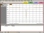
figure2.png
Figure 2

Smith Chart of Resonating Circuit
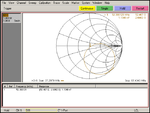
figure3.png
Figure 3


As a sanity check, I like to connect my high power Bird 50 Ohm termination to the output of my 300W PA. I monitor the S11 (reflection) using a section and it’s down in the mV (e.g. noise level).

When I connect my resonating circuit I need to adjust the signal generator to perform some minor tuning to minimize the reflected waveform.

Here is my question:
When matching, maximum power transfer occurs when Zz=ZL* (conjugate).
• In a [SIG GEN+PA+RESISTIVE LOAD] cascade this is straight forward, the power amplifier (which has a 50 Ohm characteristic impedance) terminates into a 50 Ohm Bird attenuator.

• I have a LC circuit which resonates around 52.3MHz. There are NO resistive elements, all I have are capacitors and inductors in series-parallel topology. Referring to resonators, when my circuit is resonating at 52.3MHz, by definition the reactance’s jwL and 1/jwC are of equal magnitude only leaving the resistive element.

Only reactive elements in my (built) resonating circuit.
figure4.png
Figure 4


Is the resistive element equivalent to 50 Ohms to match the impedance of the amplifier input?
If so, how is this calculated after I have determined:
figure5.png
Figure 5

In a simulation, the circuit requires around 23.7Ohm to resonate. Would this be equivalent to the ESR of the lumped elements?
figure6.png
Figure 6


Thanks for any help.
 

Another way to look at the question is...

What changes occur when you attach a high resistance?
A low resistance?

Amplitude? Bandwidth? Q?
Etc.

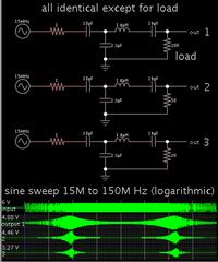
Simulations are great for examining such questions. Here is one which shows your filter's behavior with various loads.


LC component values determine whether your filter can run at high amperage, or low amperage.

Greater amperage goes with (a) a larger capacitor, or (b) smaller inductor. You need both if you wish to maintain a given center frequency.

Values are derived from the formula for inductive reactance:
XL = 2 Pi f L

and for capacitive reactance:
XC = 1 / ( 2 Pi f C )

As you may know, the calculations are not so straightforward as those for ohmic resistance.
 

So when my circuit is resonating, there is a 50 Ohm (R) component which centers it in the Smith Chart?

An LC tank presents very little impedance to its resonant frequency. Oscillations can continue for many cycles, losing energy bit by bit through each cycle.

Off-frequency it gets complicated, of course. It depends on whether a capacitor passes highs or diverts highs, and how much. It depends on how much an inductor passes lows or diverts lows, and how much.

Your filter has a capacitor diverting highs, and also a series LC inline with a resistive load.

To choose C and L values, I'm not sure if the C and L reactance should each be selected to equal the resistive load (50 ohms), or each be half of it (25 ohms). There is that vector drawing method, of course...

I know it will not necessarily work if we calculate the C which yields 50 ohms at 52 MHz, nor the L which yields 50 ohms.
 

It is, by definition, impossible to deliver real power to a perfectly imaginary load. But in reality, your resonant circuit has a real impedance to it, and that must be known to design a matching network.
 

It is, by definition, impossible to deliver real power to a perfectly imaginary load. But in reality, your resonant circuit has a real impedance to it, and that must be known to design a matching network.

So in "the real world", all the resistivity in my transmission lines and my elements some how add up to be 50 Ohm at the resonance?
 

If you remove C1, C2 and C3 and series LC connect between source and 50ohms load then at resonance you will get matched load to source like in your example in link. Capacitors 1..3 transforms source impedance to about 22.8 ohms and new load must be equal to new source impedance to be matched. Of course this is valid for single frequency or some pass band.
 

So in "the real world", all the resistivity in my transmission lines and my elements some how add up to be 50 Ohm at the resonance?
Not sure if I'm understanding your problem... are you trying to deliver power to a resonant element/network, or are you trying to use a LC network to impedance match to a resistive load (meaning you want the power delivered to the resistive load, not the LC parts)?

You keep saying "resonant" but in general when you have an LC network its resonant frequency isn't always relevant when it's used as an impedance transformer. Often the impedance match occurs at a frequency which is close, but not equal to, the resonant frequency.
 

So in "the real world", all the resistivity in my transmission lines and my elements some how add up to be 50 Ohm at the resonance?

Impedance matching allows you to obtain maximum power transfer.

The ratio L:C determines LC impedance.

Small L, large C, operates on high current. In this sense it has low impedance.

Large L, small C, needs little current. It has high impedance.

Now suppose you wish to combine the LC with an incoming (or outgoing) resistance. You will choose the L:C ratio accordingly.
 

Not sure if I'm understanding your problem... are you trying to deliver power to a resonant element/network, or are you trying to use a LC network to impedance match to a resistive load (meaning you want the power delivered to the resistive load, not the LC parts)?

You keep saying "resonant" but in general when you have an LC network its resonant frequency isn't always relevant when it's used as an impedance transformer. Often the impedance match occurs at a frequency which is close, but not equal to, the resonant frequency.

The objective is to have the whole board resonate at a certain frequency and then being able to mathematically characterize what is happening. Referring to https://en.wikipedia.org/wiki/LC_circuit#Parallel_LC_circuit , the Z-> infinity part doesn't make sense when at resonance in a 50 Ohm transmission line.

- - - Updated - - -

Impedance matching allows you to obtain maximum power transfer.

The ratio L:C determines LC impedance.

Small L, large C, operates on high current. In this sense it has low impedance.

Large L, small C, needs little current. It has high impedance.

Now suppose you wish to combine the LC with an incoming (or outgoing) resistance. You will choose the L:C ratio accordingly.

Hi BradtheRad,
I get you have stated. I just don't understand where the real impedance comes from which matches to the 50 ohm transmission line when Z-> infinity as described below.
https://en.wikipedia.org/wiki/LC_circuit#Parallel_LC_circuit
resonance.png
 

Simplified explanation is that series LC tank has 0 Ohms impedance at it's resonance frequency. But two capacitors C1...C3 forms a step down impedance transformer from 50 Ohms to 22.8 Ohm. What purpose can your circuit have?
 

where the real impedance comes from which matches to the 50 ohm transmission line

The impedance is reactive. It's due to the C opposing voltage changes, and the L opposing Ampere changes.

Furthermore when you put L and C together, it brings in all kinds of interesting effects, including resonant action.

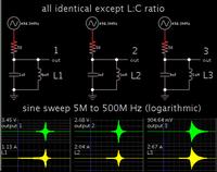
Don't know why, but I seem to be easily entertained by watching animated simulations. This one shows 3 LC tanks having the same resonant frequency. Their ratio of L:C is different. Everything else is identical.


None of the LC tanks has ohmic resistance.

Notice the second LC tank appears to be carrying the most peak watts (4W).

Doing raw math...
The first LC tank has an internal impedance of 3 ohms (at the resonant frequency).
The second, 1 ohm.
The third, 1/3 ohm.

This does not necessarily tell us how to choose an LC combination to match a 50 ohm input resistance.

It does give us a hint of the great variety of simulations that we could learn from, by trying different configurations... by adding various ohm values in the loop, or putting LC in series, or measuring current through components, etc.
 

Simplified explanation is that series LC tank has 0 Ohms impedance at it's resonance frequency. But two capacitors C1...C3 forms a step down impedance transformer from 50 Ohms to 22.8 Ohm. What purpose can your circuit have?

Hello Borber,
The purpose of the circuit is to generate very high Vrms voltages at resonance.

- - - Updated - - -

The impedance is reactive. It's due to the C opposing voltage changes, and the L opposing Ampere changes.

Furthermore when you put L and C together, it brings in all kinds of interesting effects, including resonant action.

Don't know why, but I seem to be easily entertained by watching animated simulations. This one shows 3 LC tanks having the same resonant frequency. Their ratio of L:C is different. Everything else is identical.


None of the LC tanks has ohmic resistance.

Notice the second LC tank appears to be carrying the most peak watts (4W).

Doing raw math...
The first LC tank has an internal impedance of 3 ohms (at the resonant frequency).
The second, 1 ohm.
The third, 1/3 ohm.

This does not necessarily tell us how to choose an LC combination to match a 50 ohm input resistance.

It does give us a hint of the great variety of simulations that we could learn from, by trying different configurations... by adding various ohm values in the loop, or putting LC in series, or measuring current through components, etc.

...The impedance is reactive. It's due to the C opposing voltage changes, and the L opposing Ampere changes.

I can show this on the bench (e.g. measure on the VNA) but I'm trying to characterize it. I think you're on to something with your comment about the elements cancelling out the voltage and current phases.
 

Status
Not open for further replies.

Part and Inventory Search

Welcome to EDABoard.com

Sponsor

Back
Top