Continue to Site

Welcome to EDAboard.com

Welcome to our site! EDAboard.com is an international Electronics Discussion Forum focused on EDA software, circuits, schematics, books, theory, papers, asic, pld, 8051, DSP, Network, RF, Analog Design, PCB, Service Manuals... and a whole lot more! To participate you need to register. Registration is free. Click here to register now.

How do you make timer 0 start and stop

Status
Not open for further replies.
Hmmm, I managed to watch the Youtube video, despite very slow internet here. They work on a slightly different principle to what you are trying. Before going further, can you tell me what hardware you have connected to the sensors. I need to know what there is between your TX pin and the transmitting transducer and also what you have between the receiving transducer and the RX pin. This is critical to the way it works.

I don't think the clock signal is the problem and certainly 100MHz is far higher than necessary. You present code will not loop so you can't take continuous readings. The PWM will be turned off and the program will loop forever without taking any further measurements after the first interrupt occurs. May I suggest you rearrange the code slightly like this:

1. create a global variable, lets call it "MeasurementTaken", set its value to zero.
2. in the interrupt routine, stop Timer 0 from counting, copy the values in Timer 0 to a variable, make MeasurementTaken = 1, stop the PWM.
3. in the main() routine, set up the PWM and other PIC registers.
4. set Timer 0 to zero
5. turn the PWM on.
6. start a while(1) { loop
7. use "if(MyMeasurementTaken) {report the reading in the variables you set in the interrupt routine then set MeasurementTaken = 0, clear Timer 0 then turn the PWM on again}
8. close the while loop

This will take repeated measurements between interrupts and you can take as long as needed in step 7 to report the value by LCD or serial link. Steps 4 and 5 are to ensure the first measurement is valid, from then on the same steps are taken inside the while loop but only after the MeasurementTaken variable lets it know that an interrupt occurred and they need to be prepared again.

Brian.
 

hmmm, i managed to watch the youtube video, despite very slow internet here. They work on a slightly different principle to what you are trying. Before going further, can you tell me what hardware you have connected to the sensors. I need to know what there is between your tx pin and the transmitting transducer and also what you have between the receiving transducer and the rx pin. This is critical to the way it works.

I don't think the clock signal is the problem and certainly 100mhz is far higher than necessary. You present code will not loop so you can't take continuous readings. The pwm will be turned off and the program will loop forever without taking any further measurements after the first interrupt occurs. May i suggest you rearrange the code slightly like this:

1. Create a global variable, lets call it "measurementtaken", set its value to zero.
2. In the interrupt routine, stop timer 0 from counting, copy the values in timer 0 to a variable, make measurementtaken = 1, stop the pwm.
3. In the main() routine, set up the pwm and other pic registers.
4. Set timer 0 to zero
5. Turn the pwm on.
6. Start a while(1) { loop
7. Use "if(mymeasurementtaken) {report the reading in the variables you set in the interrupt routine then set measurementtaken = 0, clear timer 0 then turn the pwm on again}
8. Close the while loop

this will take repeated measurements between interrupts and you can take as long as needed in step 7 to report the value by lcd or serial link. Steps 4 and 5 are to ensure the first measurement is valid, from then on the same steps are taken inside the while loop but only after the measurementtaken variable lets it know that an interrupt occurred and they need to be prepared again.

Brian.


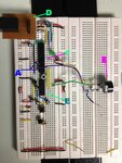
Tx.JPG

This is the transmitter circuit.
A) Output for PWM, on the pic18f2520
B) Transmitter
C) INput signal from the receiver into the pin21 of the pic18f2520
D) Cable to connect to thge icd2 debugger
E) rs232 for serial link


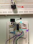
Rx.JPG


This is the receiver circuit.
A) Transmitter
B) Receiver
C) op amp to amplify the weak signal received from the receiver. Pin1 is the signal input
d) The pin 8 of the op amp is the output signal. This will go to the transmitter circuit (1st pic), on the pin21 of the pic18f2520


p18f2520 pin diagram.JPG

This is the pin diagram of my pic controller (2520)


the principles used in the video is different, my purpose is to show u the part on the results. it displays instantly, and the result changes as he moves the probe. for me now, i have to start and stop the progam so i can watch the result on the watch window. meanwhile i am trying to understand slowly your steps. but, for what i know, at the end of my interrrupt function, i have set back the interrupt flag back to=0, so it can be interrupted many times, not only 1 time.

Code:
//INTCONbits.INT0IF	=0; 	//The INT0 external interrupt CLEARED.

Am I doing it right?

If I understand what you mean, I will set it such way:

Code:
#include <p18f2520.h>		//MCU IN USE
#include <string.h>			//???
#include <timers.h>			//???
#include <stdlib.h>			//???
#include <pwm.h>			//INCLUDE PWM TIMER


int result;
int timeL;
int timeH;


void high_isr(void);				// High priority interrupt service routine
#pragma code high_vector=0x08		// High priority interrupt vector


void high_vector(void) 
{
	_asm goto high_isr _endasm		//JUMP TO INTERRUPT ROUTINE
}


#pragma code						//RETURN TO DEFAULT CODE SECTION							
#pragma interrupt high_isr


void high_isr(void) 				// high Priority Interrupt Routine
{		
	PORTBbits.RB2=!PORTBbits.RB2;   //toggle LED
	//T0CONbits.TMR0ON	=0;			//STOP COUNTER
	//result = ReadTimer0();			//READ VALUE OF COUNTER
	//timeL = TMR0L; 					//Save lower byte to variable 
	//timeH = TMR0H; 					//Save higher byte to variable


	//ClosePWM1();			 
	//CloseTimer0();
    //TMR0L=0b00000000;			//TIMER0 STARTING BITS AT 0
	//TMR0H=0b00000000;			//TIMER0 STARTING BITS AT 0
	//INTCONbits.INT0IF	=0; 	//The INT0 external interrupt CLEARED.
}


void main()
{	
	while(1)
	{
	TRISA= 0b11111111;			// I/O SETTINGS
	TRISB= 0b00000011;			// I/O SETTINGS
	TRISC= 0b10000000;			//RC7(R-X) as input & RC6(TX) as output 


	//CONFIGURE AND ACTIVATE INTERNAL OSCILLATOR
	OSCCON = 0b01110000;        //select internal clock at 8Mhz frequency
	OSCTUNE = 0b01000000;		// PLL Mode enable, Total Internal Oscillation = 32MHz 


	//TIMER0 SETTINGS
	OpenTimer0 (TIMER_INT_ON &			// On Timer0 Interrupt
			   T0_16BIT &				// 16-bits Mode
			   T0_SOURCE_INT &			// External Clock Source
			   T0_PS_1_8);				// Set Prescaler to 1:1


	//INTERRUPT SETTINGS
   	INTCON=0b00010000;			//DISABLE GLOBAL & ENABLE EXT INTERRUPT, Disables the TMR0 overflow interrupt,
	INTCON2=0b01000000;			//External Interrupt on RISING edge (BIT6)
	RCONbits.IPEN		=1;		//Enable priority levels on interrupts
	INTCONbits.GIEH		=1;		//Global Interrupt Enable


	//TIMER0 START BITS @ 0
	TMR0L=0b00000000;		//TIMER0 STARTING BITS AT 0
	TMR0H=0b00000000;		//TIMER0 STARTING BITS AT 0


	//THIS IS THE SETTING FOR THE PULSE WIDTH MODULATION
	//THIS IS IN PIN 13
	OpenTimer2(TIMER_INT_OFF & T2_PS_1_1 & T2_POST_1_1);	//OPEN PWM. PRESCALAR IS 1:1
	OpenPWM1(0xc7);	//REFER TO A FOR CALCULATION									
	SetDCPWM1(400);	//REFER TO B FOR CALCULATION


	T0CONbits.TMR0ON=1;		//START COUNTER!
	}
}

I just while(1) the whole main program, something like that?

Shahlam.
 

One of my teachers have responded to your latest suggestion. And he said this:


Hi, Shalam
You didn't tell people that the travelling time for ultrasound from transmitter to receive is only a few microsecond, did you? And the difference in time between blood and saline is only a few hundred nanosecond.
The guy don't know our situation, his suggestion is on the code, but our problem right now is not on the code. We are testing our sensor and see whether the sensor can detect the time difference between time spent in blood and the saline.
 

Question - is Neyolight the same person as Shalam or are you both students on the same course?

Your teacher is quite right about the small time differences, that's why I mentioned the phase difference method in an earlier post. To briefly explain, even under ideal conditions there will be a certain time between turning on the PWM and the transmitter reaching full power, the signal doesn't just suddenly appear at full level. Similarly, when the microphone picks the sound up, it will see a rising edge at the start of the arriving 40KHz. The time taken to reach full transmit power and for the receiver output to be able to reach the voltage needed to trigger the interrupt may be many times longer than the time you are trying to measure.

The phase measuring method is far more accurate when the time delay is very short, what you do is keep the transmitter PWM running so it is always sending the 40KHz signal out. You then look at the actual waveform from the receiver rather than just seeing if it's there or not. The waveform will be a delayed copy of the transmitter signal, it would look the same shape but if you plotted the two signals on a graph against a time axis you would see the waveforms were out of step because one was delayed by the distance and medium the signal had traveled through. As the delay changes, the waveforms would move relative to each other, in other words their relative phases change. The task is then to measure the amount of phase change. This is actually easier than it sounds because there is a very simple way of converting phase differences to a measurable signal, all you do is use the logic XOR function with one input being the PWM and the other the signal from the microphone. You can implement the XOR in software or as a simple electronic circuit. The magical property of XOR is it's output is only high when there s a difference between it's two input signals, so it is proportional to the differences in their phase.
You can measure this in two ways, by filtering the XOR output and measuring the analog voltage it produces or by using a timer to measure the length of the difference signal.

The drawback to using this method is the result is cyclical, it can't detect which cycle it is comparing, it will give the same result if the delay is say, half a cycle, one and a half cycles and two and a half cycles and so on. The way around this is to use your original method to get the approximate delay then switch to the phase method to 'fine tune' the result.

Going back to your code, yes, the while(1) will now work although you don't need to include all the main() function inside it, the part that sets up the registers doesn't need to be repeated. Where your original code failed was that it sat in a tight loop repeating only the while(1) instruction. Yes, the interrupt would still have been processed but it would return back to the while() loop when it completed so there was nowhere a fresh PWM signal could be generated. Remember you were looking for the delay between the start of the 40KHz being sent and it arriving back to cause the interrupt so each time you took a measurement it was necessary to turn off the PWM in order to create a new 'front edge' for it to detect again.

Incidentally, I can't see any decoupling capacitors on your circuit boards, you should fit several capacitors (10uF and 0.1uF) across the ground and supply connections to ensure the PIC and amplifiers work reliably.

Brian.


Hi Brian,

Thanks alot with the suggestion. My teacher said it was a good idea. Currently I am trying to use it. For now, I managed to output the results to the hyper terminal. But the results given were to fast. So my other teacher suggested to take the every 100 results, then only display the average. Atleast the results displayed is slightly slower so I can easily monitor it. But the problem now, is how do I take every 100 result, store, compute the average, and display it, and then clear back the value stored, and start storing new 100 results? I know must use array, but since it is in the interrupt function, I can't put 'do while' in the interrupt function as the cpu needs to clear bits, exit the interrupt func, then wait for another interrupt, take 2nd results. I am headache trying to figure a way out. I hope I don't have to use another interrupt..

This is my updated code

Code:
#include <p18f2520.h>		//MCU IN USE
#include <string.h>			//???
#include <timers.h>			//???
#include <stdlib.h>			//???
#include <pwm.h>			//INCLUDE PWM TIMER
#include <usart.h>


int channel_one;
char hundreds[11]={'0','1','2','3','4','5','6','7','8','9','T'};
char tens[10]={'0','1','2','3','4','5','6','7','8','9'};
char no[10]={'0','1','2','3','4','5','6','7','8','9'};


int flag=0;
int result1=0;


void high_isr(void);				// High priority interrupt service routine
#pragma code high_vector=0x08		// High priority interrupt vector


void high_vector(void) 
{
	_asm goto high_isr _endasm		//JUMP TO INTERRUPT ROUTINE
}


#pragma code						//RETURN TO DEFAULT CODE SECTION							
#pragma interrupt high_isr


void high_isr(void) 				// high Priority Interrupt Routine
{		
	PORTBbits.RB2=!PORTBbits.RB2;   //toggle LED
	T0CONbits.TMR0ON	=0;			//STOP COUNTER
	result1 = ReadTimer0();			//READ VALUE OF COUNTER


	while (BusyUSART());	       	// ensure the serial port is not busy
    WriteUSART('s');
    while (BusyUSART());
	WriteUSART(hundreds[(result1/100)]);
    while (BusyUSART());
	WriteUSART(tens[(result1%100)/10]);
	while (BusyUSART());
	WriteUSART(no[(result1%100)%10]);


	SetDCPWM1(0);				//Disable PWM		 
	TMR0L=0b00000000;			//TIMER0 STARTING BITS AT 0
	TMR0H=0b00000000;			//TIMER0 STARTING BITS AT 0
	INTCONbits.INT0IF	=0; 	//The INT0 external interrupt CLEARED.
    flag=1;
  }


void main()
{	
	result1=0;
	result2=0;
	TRISA= 0b11111111;			// I/O SETTINGS
	TRISB= 0b00000011;			// I/O SETTINGS
	TRISC= 0b10000000;			//RC7(R-X) as input & RC6(TX) as output 
	
	PORTBbits.RB2=0;


	//CONFIGURE AND ACTIVATE INTERNAL OSCILLATOR
	OSCCON = 0b01110000;        //select internal clock at 8Mhz frequency
	OSCTUNE = 0b01000000;		// PLL Mode enable, Total Internal Oscillation = 32MHz 


	//TIMER0 SETTINGS
	OpenTimer0 (TIMER_INT_ON &			// On Timer0 Interrupt
			   T0_16BIT &				// 16-bits Mode
			   T0_SOURCE_INT &			// External Clock Source
			   T0_PS_1_1);				// Set Prescaler to 1:1


	OpenUSART(USART_TX_INT_OFF &			// Transmitter Interrupt Off
			USART_RX_INT_OFF &			// Receiver Interrupt Off
			USART_ASYNCH_MODE &			// Set USART to Asynchronous Mode
			USART_EIGHT_BIT &			// 8-bits Data
			USART_CONT_RX &				// Continuous Reception
			USART_BRGH_HIGH,103);		// High Speed Rate and Baud Rate = 19200 {(32000000/19200*16)} - 1


	//INTERRUPT SETTINGS
   	INTCON=0b00010000;			//DISABLE GLOBAL & ENABLE EXT INTERRUPT, Disables the TMR0 overflow interrupt,
	INTCON2=0b01000000;			//External Interrupt on RISING edge (BIT6)
	RCONbits.IPEN		=1;		//Enable priority levels on interrupts
	INTCONbits.GIEH		=1;		//Global Interrupt Enable


	//TIMER0 START BITS @ 0
	TMR0L=0b00000000;		//TIMER0 STARTING BITS AT 0
	TMR0H=0b00000000;		//TIMER0 STARTING BITS AT 0


	//THIS IS THE SETTING FOR THE PULSE WIDTH MODULATION
	//THIS IS IN PIN 13
	SetDCPWM1(400);	
	OpenPWM1(0xc7);										
	OpenTimer2(TIMER_INT_OFF & T2_PS_1_1 & T2_POST_1_1);	//PRESCALAR IS 1:1


	T0CONbits.TMR0ON=1;		//START COUNTER!


	while(1)
		{
		if(flag==1)
			{
			SetDCPWM1(400);
			T0CONbits.TMR0ON=1;
			}
		}
	
}	//END OF MAIN


Hope to hear from you soon. And I don't know who is Neyolight.

Norulshahlam (short name's shahlam)


Question - is Neyolight the same person as Shalam or are you both students on the same course?

Brian.

Heya. I am only registered as "Neyolight" on this forum. :) Why on earth would I use two accounts for posting problems? Its difficult remembering password for one account.

But what made you think we are one ? *Confused*

---------- Post added at 13:23 ---------- Previous post was at 13:18 ----------

I cannot be doing the same course as shalam as Im studying masters. I dont have any courses in masters, only research work and lots of wandering around and going in circles for weeks ! I dont know shalam :)
 

Sorry Neyolight, please don't take offense. The name in the thread changed but the topic seemed to stay the same so I wasn't sure who I was replying to.

Shalam, thanks for the video and I 'm sorry I couldn't reply sooner, I have a building company working here at the moment and they keep cutting the electricity off which makes emailing a bit difficult!
The way to take averages is simply to add each reading until you have done it 100 times then set a flag to trigger the display routine. I assume the 'ReadTimer0() is a function in your compiler library that returns a 16-bit value, so declare 'result' as a 'double' or 'long int' to hold the result then use:
Code:
result += ReadTimer0();
NumberOfReadings++;

In the main program loop, check if enough readings have been totalled by using:
Code:
if(NumberOfReadings == 100)
{
 NumberOfReadings = 0;
 <routine to send result/100 to the USART>
}

Part of your problem is that the USART is itself a timed element, each time a character is sent, it has to wait for it to be clocked out of the TX pin and for the transmit register to be reported as empty. You are doing this inside a the interrupt routine so it causes a relatively long delay and several interrupts may occur while you are reporting the result. As a general rule in all programming, keep your interrupts routines as short as possible because by their nature, they are invoked because something needs immediate attention. Some code is inevitable but if you can do the slower jobs like sending to the serial port in the normal (non-interrupt) part of the program where there is more time to spare, it usually works out better.

I'm not sure your character arrays are necessary, does your compiler have a formatted print function (sprintf or printf) to convert numbers to characters for you? For example, you send 's' followed by the result, could you use something like:
Code:
sprintf(DisplayText,"s%d/n",result/100);
WriteUSART(DisplayText);

To format the result into a character string 'DisplayText' then send it to the PC. I may not have the exact function names correct for your compiler but there should be something similar, your tutor should be able to help with the function to send a string to the USART.

Brian.


Hi Brian,

I thought you totally ignore me, as you didn't reply me for quite sometime. I happen to browse through the forum and try to look back your past suggestions then I saw you have replied me! Strange I didn't receive in my email that you had reply. Well no need for sorry, I'm still thankful for your help all this while although I am still stuck at the same level.


Well, my teacher is suggesting another method. The phase shift method is our worry as we don't think my microcontroller is fast enough to capture the 'super split seconds' hence I am needed to capture the frequency changes only, based on 'doppler effect'. Using the CCP Capture function, and some tips and tricks, I managed to write a totally new code. I use this capture function as I only need to measure the input frequency. After using function generator and test it to the input pin of the MCU, the results I got was different from what I pump into the pin.

Code:
#include <p18f2520.h>		//MCU IN USE
#include <string.h>			
#include <timers.h>			
#include <stdlib.h>			
#include <pwm.h>			//INCLUDE PWM TIMER
#include <usart.h>
#include <capture.h>


int channel_one;
char tenthousands[10]={'0','1','2','3','4','5','6','7','8','9'};
char thousands[10]={'0','1','2','3','4','5','6','7','8','9'};
char hundreds[10]={'0','1','2','3','4','5','6','7','8','9'};
char tens[10]={'0','1','2','3','4','5','6','7','8','9'};
char no[10]={'0','1','2','3','4','5','6','7','8','9'};


float average,sum, period;
int result=0;
int result_previous=0;
int T;


void high_isr(void);				// High priority interrupt service routine
#pragma code high_vector=0x08		// High priority interrupt vector


void high_vector(void) 
{
	_asm goto high_isr _endasm		//JUMP TO INTERRUPT ROUTINE
}
#pragma code						//RETURN TO DEFAULT CODE SECTION							
#pragma interrupt high_isr


void high_isr(void) 		// high Priority Interrupt Service Routine
{		
	PIR1bits.CCP1IF=0;		//CCP1 INTERRUPT REGISTER CAPTURE OCCURED
	PIR2bits.TMR3IF=0;		//TIMER3 OVERFLOW OCCURED
	
	if(!CapStatus.Cap1OVF)
	result= ReadCapture1();	//READ VALUE OF COUNTER
}	


void main(void)
{
	INTCONbits.GIEH=0;		//DISABLE GLOBAL INT
	
	TRISA= 0b11111111;			// I/O SETTINGS
	TRISB= 0b00000011;			// I/O SETTINGS
	TRISC= 0b10000100;			//RC7(R-X) as input & RC6(TX) as output 
								//RC2=INPUT


	//CONFIGURE AND ACTIVATE INTERNAL OSCILLATOR
	OSCCON = 0b01110000;        //select internal clock at 8Mhz frequency
	OSCTUNE = 0b01000000;		// PLL Mode enable, Total Internal Oscillation = 32MHz 


	// Configure Capture1
	OpenCapture1( C1_EVERY_RISE_EDGE &
					CAPTURE_INT_ON );


	// Configure Timer3
	OpenTimer3(TIMER_INT_ON &
	T3_16BIT_RW &
	T3_SOURCE_INT &
	T3_PS_1_8 &
	T3_OSC1EN_ON &
	T3_SYNC_EXT_ON &
	T3_SOURCE_CCP );


	OpenUSART(USART_TX_INT_OFF&	// Transmitter Interrupt Off
	USART_RX_INT_OFF &			// Receiver Interrupt Off
	USART_ASYNCH_MODE &			// Set USART to Asynchronous Mode
	USART_EIGHT_BIT &			// 8-bits Data
	USART_CONT_RX &				// Continuous Reception
	USART_BRGH_HIGH,103);		// High Speed Rate and Baud Rate = 19200 {(32000000/19200*16)} - 1


	//INTERRUPT SETTINGS
	RCONbits.IPEN=1;		//ENABLE PRIORITY INT
   	IPR1bits.CCP1IP=1;		//HIGH PRIORITY BIT
	INTCONbits.GIEH=1;		//ENABLE GLOBAL INT
	PIE1bits.CCP1IE=1;	  	//ENABLE CCP1 INT


while(1)
{		
	if (PIR1bits.CCP1IF==0)	//IF CAPTURE OCCURED,
	{   
		PORTBbits.RB2=!PORTBbits.RB2;
		result_previous=result;
		T = result-result_previous;
 		
		while (BusyUSART());	    	   	// ensure the serial port is not busy
   		WriteUSART(' ');					//sent data to hyper terminal link thru com1
		while (BusyUSART());				// ensure the serial port is not busy
		WriteUSART(hundreds[(T/100)]);		//sent data to hyper terminal link thru com1	
   		while (BusyUSART());				// ensure the serial port is not busy
		WriteUSART(tens[(T%100)/10]);		//sent data to hyper terminal link thru com1
		while (BusyUSART());				// ensure the serial port is not busy
		WriteUSART(no[(T%100)%10]);			//sent data to hyper terminal link thru com1
		while (BusyUSART());	       		// ensure the serial port is not busy
 		WriteUSART(' ');					//sent data to hyper terminal link thru com1

		if(PIR2bits.TMR3IF==0)	//IF TIMER3 OVERFLOWS, RESET IT
		TMR0L=0b00000000;
		TMR0H=0b00000000;
	}
}
		
}//END OF MAIN

Hoping to hear from you soon..

Shahlam
 

Doppler shift measurement will not work. The Doppler effect is the perceived shift in frequency because the waves appear to be compressing as the distance reduces or expanding as the distance increases. As soon as the change in distance stops, so does the shift. In other words it is not suitable to measure distance or media density, it can only be used to measure rate of motion.

Going back to your teachers comment a few messages back, they suggest that the real problem is in the hardware and not wholly in software. I agree with them although in a real life application a designer would be expected to find the lowest cost solution to the problem and software is much less expensive than hardware. A little of both is needed.

You should realize that the time taken to process each microprocessor instruction can make a significant difference in the delay you measure. Interrupts are usually the fastest way to respond to an external event such as the echo of your ultrasound but they take time to save program status and call the ISR. Luckily, the time sent entering the ISR will probably be the same each time so it should be possible to adjust the result to compensate for this delay.

I have not done any experimenting to test anything I have suggested so please accept what I tell you as theory, not a proven technique.

Your last code may be useful but not in the way you think. I would still go for phase measurement and an XOR gate to produce the difference between transmitted and received waves. I havent checked to see if the PWM and capture can be used at the same time in your PIC, if they can't, try using a difference frequency source for your transmitter, possibly divided down from the PIC crystal oscillator so it is very stable. Use the CCP module to time the duration of the pulses from the XOR gate, the measurement shoulfd be proportional to the delay between transmitted and received signals. You can then use math to convert the duration into a meaningful number before displaying it. Please also check to see if your compiler has a function to format numbers (sprintf?) to make your display routine simpler.

Brian.
 

Status
Not open for further replies.

Similar threads

Part and Inventory Search

Welcome to EDABoard.com

Sponsor

Back
Top