Continue to Site

Welcome to EDAboard.com

Welcome to our site! EDAboard.com is an international Electronics Discussion Forum focused on EDA software, circuits, schematics, books, theory, papers, asic, pld, 8051, DSP, Network, RF, Analog Design, PCB, Service Manuals... and a whole lot more! To participate you need to register. Registration is free. Click here to register now.

how do we measure the value of an inductor at constant current ?

Status
Not open for further replies.

muhibraza

Member level 1
Joined
Oct 11, 2010
Messages
38
Helped
3
Reputation
6
Reaction score
3
Trophy points
1,288
Activity points
1,578
hello
I have winded 27 turns on a toroid now I want to find its inductance at 1 Ampere dc current. what is the method for doing this ?
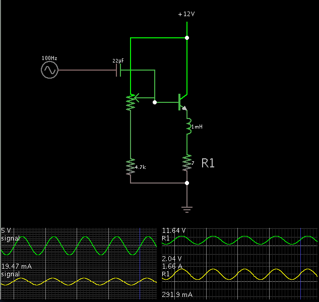
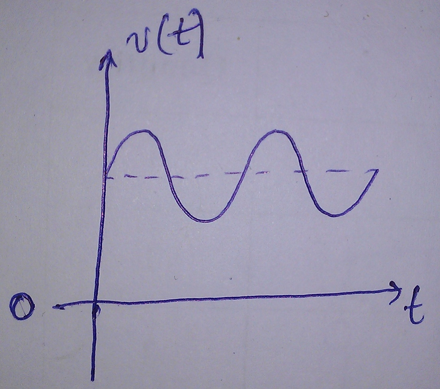
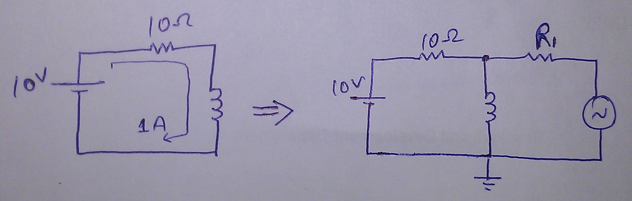
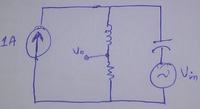
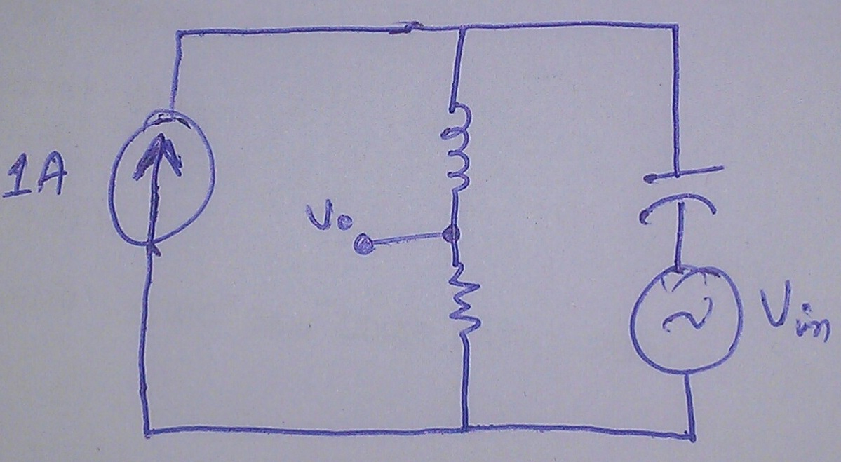
I previously measured the inductance by an RL filter and its cutoff frequency formula but I measured it on sine wave with no dc component. I now need a DC offset too that results in 1 Ampere current flowing through the RL filter, then I would superimpose the 10V (peak) sin wave and find the value of L using the same formula. The main thing is that 1 ampere current but I dont know how to implement the circuit. I have to make the following circuit. I do not have a bench current source but I do have a voltage source :


any help would be appreciated
 

Do you want the output to be entirely in the positive polarity? Then a single transistor can be adjusted to send 1A DC through a load.

Apply the AC signal to the base of the transistor. Then it rides the DC voltage which is applied to the coil.

The supply voltage must be great enough to accommodate the voltage swing of your incoming signal.


Thanks for the reply.
But I was thinking that the back emf would destroy the transistor and power supply too. I can use a diode to suppress it but if I do so, wouldnt the ac signal be disturbed too in terms of wave shape ?

- - - Updated - - -

by the way which software do you use ? looks good.
 

I would feed your 1A via a 10 ohm (10W) resistor through your coil. Feed your AC via a resistor into the junction of the coil and resistor. Measure the voltage drop across the resistor to calculate the AC current, you know the AC voltage, so you can work out the AC impedance, from this you can work out what inductance in parallel with ten ohms equals this impedance.
Frank
 

Dear chuckey,
I am sorry I dont understand what you said. How can you feed 1 A via a 10 Ohm resistor through the coil at the same time you talk about the resistor and inductor being parallel ?
Can you post an image of the circuit if possible ?
 

but the circuit I want to make involves a current source not a voltage source. Meaning, I would assume the Dc current source an open circuit for ac analysis. Then how could the inductor and resistor be in parallel ?
 

Chuckey suggested to use a DC voltage source along with the 10 ohm resistor, a practical setup with standard components and instruments.

Otherwise you need to design a current source with +/- 10V compliance. That's feasible of course, but requires some design and assembly work. A LM337 with suffcient heatsink and a 1.2 ohm shunt e.g. would do.
 

"Chuckey suggested to use a DC voltage source along with the 10 ohm resistor, a practical setup with standard components and instruments."

If the limiting resistor has a resistance of 20 to 100 times that of the load being tested (your inductor) and is fed with a regulated voltage, its performance is close enough to an ideal current source.

I Once worked at a Sylvania factory which made vacuum tubes (valves). One part of the process requires aging the heater at constant current. Remember, this was 40 years ago, power transistors were still fragile and expensive.

The solution for 6.3 volt heaters, was to add a large resistor that would drop about 113 volt in series with the heater, and feed it up from regulated AC voltage from a ferroresonant transformer. (the resistance was 18 times as large).

Of course, nowadays, you can always design a good constant current source.
 

Thanks for the reply.
But I was thinking that the back emf would destroy the transistor and power supply too. I can use a diode to suppress it but if I do so, wouldnt the ac signal be disturbed too in terms of wave shape ?

It is true that when you stop current flow suddenly, the coil generates counter-emf, and it can spike to a high voltage. Therefore you must use caution not to disconnect any wire (or create sudden high impedance) until you have turned down your supply to 0V. It is wise to reduce your AC signal to 0V amplitude as well.

Or else by installing a diode across the coil, as is commonly done. The diode will absorb the juice coming from the coil as the flux field collapses.

The diode will not conduct if coil current is only varying DC. So it will not distort the waveform.

However, as you state, the diode will distort the waveform if your AC signal has great enough amplitude to create alternating current in the coil.

by the way which software do you use ? looks good.

I used Falstad's simulator. Free to download and use.

www.falstad.com/circuit
 

However, as you state, the diode will distort the waveform if your AC signal has great enough amplitude to create alternating current in the coil.

Ok and if I introduce a DC component which makes the signal vary in postive side only, would it be fine to use a diode for back emf suppression ?

I mean a signal like this :


Now I think if I use a diode in parallel with the inductor then it would always be reversed biased (when in operation) because the signal does not alternate negatively. The diode will never be forwarded and so the waveform will not be clipped. Am I right ? Please correct me if I am wrong

- - - Updated - - -

Chuckey suggested to use a DC voltage source along with the 10 ohm resistor

Ohhhh... Okay thats fine... I thought he was feeding it with current source... okay now correct me if I am wrong, is this the circuit which he has proposed ?


Oh and by the way the back emf problem, would there be this problem or not ?
 

"Back emf" often drifts to a vague term. The problem should be better discussed in terms of voltage and current.

For the current source case, "compliance" is the characteristic property. Referred to ground, it must be able to source the programmed current over a +/- 10 V range, of course without damage and also without current variations.

The voltage source in the two resistor circuit would be loaded with an AC current, but with the suggested settings, the total current is unipolar, as required by most lab supplies. A certain problem is, that you can't simply adjust the DC current down to zero without risking to feed the DC source backwards. But you can increase the DC feed resistor, or connect a large filter capacitor parallel to the DC supply to absorb the AC currents.

A diode across the inductor would clamp all larger AC voltages and most likely ruin the intended measurements.
 

For the current source case, "compliance" is the characteristic property. Referred to ground, it must be able to source the programmed current over a +/- 10 V range, of course without damage and also without current variations.

Basically I dont have a current source setup with me right now.
I will implement it using the voltage source and 10 ohm resistor (if I do with this method, otherwise the transistor method is also good as suggested by BradtheRad)

Okay so you say that the diode will clamp the AC voltages, but the clamp is actually needed. I just want to know would it just clamp the sine wave or would it disturb the wave shape too ?

Plus, the capacitor method is good too. I'll see this too. But right now I want to know about the wave shape thing.

- - - Updated - - -

Actually I think we have found two methods for implementing this, one is the transistor method (suggested by BradtheRad) and the other one suggested by Chuckey.

Now can anyone propose protection techniques ? should I use a capacitor or should I use a diode for dc voltage source protection ? (I'm talking about both of the suggested circuits)
 

Status
Not open for further replies.

Part and Inventory Search

Welcome to EDABoard.com

Sponsor

Back
Top