bmalbusca
Newbie level 5
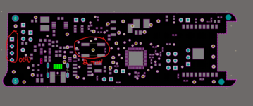
I'm attempting to align some components, such as an OLED display and a push-button, to the pcb board's centerline. The board was imported as STEP from Solidworks and has a non-uniform format (not a rectangle). The issue is that I've already completed the layout and origins from CAD to Altium have been forgotten, making it nearly impossible to insert a board shape from Soldiworks with origin marks that matches exactly to the existing board shape. Another issue I'm having is that because the board has a strange shape, it's difficult to manually set the origin because even when I click over a line, it's not right on top of it when I zoom in (has always a offset). The same principle applies when I try to mark the PCB's boundaries with simple pads or taking measures, which is the CADish way I explored to center an object between the board's lateral edges (horizontal boundaries), for example. Is there a different way to find the board's center and/or a way to place components on centerlines, midpoints or in the center of an component? When designing footprints (pcb library view) there is an option to center the origin between the existing pads but not on the layout. To get a more precise placement, I manually check the coordinates between the keep-out lines on the board edges and then make calculations, but this is not practical or error-proof.
[Moderator action: removed link to external file server]
[Moderator action: removed link to external file server]
Last edited by a moderator: