chirag2239
Member level 3
Hello,
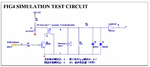
I have attached a circuit here. Please check and let me know, how I can use IFT? I mean I have connected IFT as per the circuit.
While driving the Ultrasonic sensor through transistor by providing PWM pulses of 40kHz, I should get the voltage at output of IFT. I have checked its resistance at both the end. Lower resistance would be secondary and higher resistance would be primary as this is a kind of step up transformer. This is necessary because US transceiver works on 150Vpp 40kHz frequency.
First I was having problem with transistor that was not getting switched properly. It was giving just 0.8V between collector and emitter. After changing, I am receiving 5V between collector and emitter. But still not sure it is working or not as I have applied 12V to IFT.
Can anyone help me to resolve this issue of not getting the output voltage of 150Vpp? How can I use this? Am I right in selecting the primary and secondary windings? How can I drive the Ultrasonic sensor? The main problem is that I am not getting any voltage on Transmitter pin of Ultrasonic Transceiver.
Looking for help.
Thanks.
Chirag