Continue to Site

Welcome to EDAboard.com

Welcome to our site! EDAboard.com is an international Electronics Discussion Forum focused on EDA software, circuits, schematics, books, theory, papers, asic, pld, 8051, DSP, Network, RF, Analog Design, PCB, Service Manuals... and a whole lot more! To participate you need to register. Registration is free. Click here to register now.

How can I make my own receiver?

Status
Not open for further replies.

psurya1994

Member level 5
Joined
Jun 29, 2012
Messages
86
Helped
3
Reputation
6
Reaction score
3
Trophy points
1,288
Activity points
1,807
I want to a receiver similar to that of the TSOP receiver which detects infrared waves at the frequency of 50KHz. This receiver should output a voltage of 0V when the wave is not received and output 5V when the wave is received.
I am planning to make the transmitter using a 555timer in astable mode, would it be fine?
 

TSOP1730 30 kHz TSOP1733 33 kHz
TSOP1736 36 kHz TSOP1737 36.7 kHz
TSOP1738 38 kHz TSOP1740 40 kHz
TSOP1756 56 kHz

**broken link removed**
 

Can we achieve this with a 5V supply?
220px-555_Astable_Diagram.svg.png
Why don't we use the above simpler circuit?
Can we build our own receiver?
The problem with TSOP is that it doesn't output 0 or 1, it output 5 and 2.5 or something like that.
 
Last edited:

CMOS version of 555 has relatively lower source (10mA) and Sink(100mA) current than NE555. Single-Supply Operation From 2 V to 15 V.
Check datasheet for output current at 5Volt.
NE555 has higher op current. So its possible to use Ip IR diodes directly. But check parameters at 5 volt.
By the way, at this high frequency operation no need to add current limiting resistors.

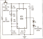
Below are the tested circuits.

trans.pngreceiver.png
 
Last edited:
Which receiver should i use because TSOP doesn't provide what i exactly want.
 

Which receiver should i use because TSOP doesn't provide what i exactly want.

In your previous posts you have mentioned that you want 1 and 0 from the TSOP output. That can be done using comparator. What is your actual application?
 

My application is that the LED should switch on when the wave is detected and should go off when it isn't. I want it to be like 50KHz so that it doesn't interfere with the TV remote signal. (56KHz will do, I can use TSOP 1756).

Ya, I tried using the comparator. It didn't work because the output of the TSOP (TSOP gives 5V when the wave isn't detected) when the wave is detected is not 2.5 actually, it is a series of pulses(just like a clock signal).
 

Ya, these pages have been very helpful to me. But I have some doubts on Infra-red remote control:
What is the frequency of the emitted wave? Is it always glowing? How can I avoid interference with TV remote?

General clarification:
The emitter we use in TV remotes is an infrared led which blinks at 38KHz frequency. (receiver is TSOP 1738)
When we are working with TSOP 1756, can we use the same infrared LED as transmitter?
 

A commercial remote control blinks the led in a sequence of long and short pulses. Each command has a different sequence.

The frequency works out to about 38 KHz in yours. In others it may be 40 KHz, etc.

You can use the same type of led to transmit 50 KHz.

Or do you mean the exact same led that is inside a remote control? And you want to add on your circuit? To do this will require exercising some careful cooperation.
 

Ya, I actually broke one of my old remotes and took the LED from there. So I have the LED.
If I use 50KHz to transmit, which receiver should I use?(Its should react only to 50KHz infrared Wave)
 

My application is that the LED should switch on when the wave is detected and should go off when it isn't. I want it to be like 50KHz so that it doesn't interfere with the TV remote signal. (56KHz will do, I can use TSOP 1756).

Ya, I tried using the comparator. It didn't work because the output of the TSOP (TSOP gives 5V when the wave isn't detected) when the wave is detected is not 2.5 actually, it is a series of pulses(just like a clock signal).

If you want that "the LED should switch on when the wave is detected and should go off when it isn't" -- That can be performed easily by connecting the output pin to a PNP transistor acting as a switch. You will get hints from the receiver circuit posted above. Also to operate the Transmitter at 56KHz is also no problem. Calculate NE555 Astable frequency using a calculator(available online) [check high time and low time].
 

If you want that "the LED should switch on when the wave is detected and should go off when it isn't" -- That can be performed easily by connecting the output pin to a PNP transistor acting as a switch. You will get hints from the receiver circuit posted above. Also to operate the Transmitter at 56KHz is also no problem. Calculate NE555 Astable frequency using a calculator(available online) [check high time and low time].

Ya, I can make the emitter of 56KHz. But can you specify which receiver posted above should I be using to detect this 56KHz wave? If possible, provide the exact circuit diagram.
Thanks
 

Ya, I can make the emitter of 56KHz. But can you specify which receiver posted above should I be using to detect this 56KHz wave? If possible, provide the exact circuit diagram.
Thanks

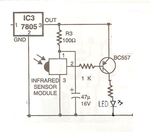
Use the following diagram. You can use TSOP1756 or 1738 etc depending upon your transmitter.

re1.png

The resistance connected to the LED is limiting the current. You can use 330 Ohm.
 
Okay.
While generating a wave of 50KHz frequency using 555 timer, to make the duty cycle to 50%, i have to make R1 zero.. Will it be fine if I make R1 zero?220px-555_Astable_Diagram.svg.png

- - - Updated - - -

I'm not sure if i will be able to get the 56KHz frequency exactly(using standard values) .. Will it be a problem? How to overcome it?
 

Use the following diagram. You can use TSOP1756 or 1738 etc depending upon your transmitter.

View attachment 76727

The resistance connected to the LED is limiting the current. You can use 330 Ohm.

Will the circuit still work if i use a pnp transistor other BC557?
Why generally all the circuits have fixed transistors to use? Will they work if we use another transistor?
 

You can replace a transistor by another if it:-
1) Match the current gain.
2) Match the maximum collector gain
 

Okay. What about R1, is it fine if i make it 0(i will short those pins)?
 

No. R1 should be 1K. and Place a preset for R2.
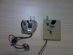
2012-07-03 20.08.42.jpg

- - - Updated - - -

Picture shows 38KHz transmitter and receiver using TSOP1738
 
Ya! I will try this one. Thanks.
And I have an other small doubt. I am doing all my circuits on a breadboard. You use a circuit board? What are the advantages? Do you have to do welding?
 

Status
Not open for further replies.

Part and Inventory Search

Welcome to EDABoard.com

Sponsor

Back
Top