Continue to Site

Welcome to EDAboard.com

Welcome to our site! EDAboard.com is an international Electronics Discussion Forum focused on EDA software, circuits, schematics, books, theory, papers, asic, pld, 8051, DSP, Network, RF, Analog Design, PCB, Service Manuals... and a whole lot more! To participate you need to register. Registration is free. Click here to register now.

How calculate gain of this opamp circuit?

Status
Not open for further replies.

yikes

Newbie level 4
Joined
Mar 2, 2012
Messages
6
Helped
0
Reputation
0
Reaction score
0
Trophy points
1,281
Location
Spain
Activity points
1,349
Hi all...

Anyone know how to calculate the gain of the attached circuit?
It is a piece of schematic from a servo controller. In reality there are some transistor between the mosfet and the opamp. I have drawn the mosfet directly for simplification.
As a student, i am interested in understanding the opamp circuit. A friend of me told me that it is possible R1, C1 and C2 are for compensation to reduce ringing or overshoots. But we don´t know how to calculate the gain of this circuit. R5 is a shunt for current measurement.

Thanks

circuit.jpg
 

Hi all...

Anyone know how to calculate the gain of the attached circuit?
It is a piece of schematic from a servo controller. In reality there are some transistor between the mosfet and the opamp. I have drawn the mosfet directly for simplification.
As a student, i am interested in understanding the opamp circuit. A friend of me told me that it is possible R1, C1 and C2 are for compensation to reduce ringing or overshoots. But we don´t know how to calculate the gain of this circuit. R5 is a shunt for current measurement.

Thanks

View attachment 75755

Seeing the cap in the feedback path tells you that you have an additional pole in the closed-loop response. This will give you the effect of integrating the input signal (a square wave will turn into a triangle-wave if the integration time is long enough).
https://www.allaboutcircuits.com/vol_3/chpt_8/11.html

If you think about how to change a square pulse into the triangle, you'd accomplish it by removing the sharp corners... effectively "softening the edges" of the square wave. This is in line with your friend's theory.

As for calculation of the gain, it will be frequency dependent, since capacitors present an impedance that varies with frequency (recall Zc = 1/jwC where w = 2*pi*freq). If you don't want to take the time to push a pencil, throw the circuit into a simple circuit simulator (LTSPICE is free), and run an AC analysis to see the gain vs. frequency response.
 
  • Like
Reactions: yikes

    yikes

    Points: 2
    Helpful Answer Positive Rating
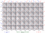
using a nomograph in less than a minute I see a 10:1 attenuator on input with LPF @ 10KHz with unit gain voltage but current feedback gain with freq of 100 x 0.1Ω = 10x current gain loop > 5MHz HPF. so the output has more drive to get current edges to match the LPF voltage which is 10% of input voltage. so in effect if is a voltage amplifier to drive the gate with gain of 10% and current amplifier > 5MHz with gain of 1x input on edges differentiated @ 5MHz. input voltage, V+, Q1 and load Z impedance characteristics need to be defined to give large signal response on load. If too capacitive phase margin will suffer and tend to overshoot and ring.
Frequency - Reactance Nomograph.gif
used since 1975 when quick answers needed in lab.
 
Last edited:
  • Like
Reactions: yikes

    yikes

    Points: 2
    Helpful Answer Positive Rating
Status
Not open for further replies.

Similar threads

Part and Inventory Search

Welcome to EDABoard.com

Sponsor

Back
Top