Continue to Site

Welcome to EDAboard.com

Welcome to our site! EDAboard.com is an international Electronics Discussion Forum focused on EDA software, circuits, schematics, books, theory, papers, asic, pld, 8051, DSP, Network, RF, Analog Design, PCB, Service Manuals... and a whole lot more! To participate you need to register. Registration is free. Click here to register now.

Homework help

ahmetkara4635

Newbie level 5
Joined
May 1, 2024
Messages
10
Helped
0
Reputation
0
Reaction score
0
Trophy points
1
Activity points
83
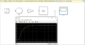
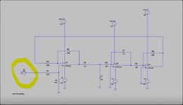
First of all, hello. I want your help with an assignment. The assignment given to me for the control systems course is to design a lead compensator. For this, I first need to design the circuit of the plant given to me. My plant is 5/s*(s+9).
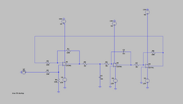
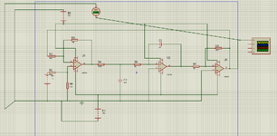
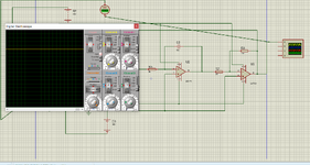
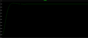
For this, I first took my simulink output. Then, I tried to implement this circuit with an integrator, a low pass filter and a differential receiver opamp. While my circuit works in LTspice it doesn't work in reality and Proteus. Can you tell me if I missed a point or something I should pay attention to while implementing my circuit?
Below are my outputs.
 

Attachments

  • Simulink.PNG
    Simulink.PNG
    59.4 KB · Views: 35
  • Lead-Ltspice.PNG
    Lead-Ltspice.PNG
    20.7 KB · Views: 30
  • Lead-Ltspice1.PNG
    Lead-Ltspice1.PNG
    15.1 KB · Views: 30
  • lead-proteus.PNG
    lead-proteus.PNG
    87.6 KB · Views: 25
  • Lead-proteus1.PNG
    Lead-proteus1.PNG
    173.6 KB · Views: 26
In reality, how have you implemented your circuit? Are you using a breadboard or have you made a PCB? PCBs may have manufacturing errors, breadboards sometimes are internally defected.
 
In reality, how have you implemented your circuit? Are you using a breadboard or have you made a PCB? PCBs may have manufacturing errors, breadboards sometimes are internally defected.
The breadboard.

I tried it many times, but I did not encounter any results other than a very weak sine, noise or constant 12.4 Vdc. I think I overcame the Vdc problem by using a practical integrator, but I still can't get any results.
 
Here is my input signal. When I apply pulse to the input, I get the result I expect. But when I installed it on the board, which I tried many times, I couldn't get much.
 

Attachments

  • Lead-Ltspice2.PNG
    Lead-Ltspice2.PNG
    33 KB · Views: 21
Here is my input signal. When I apply pulse to the input, I get the result I expect. But when I installed it on the board, which I tried many times, I couldn't get much.
* Please, can you tell us something about the result you expect as a "pulse" response?
Are you really speaking about a "pulse" or do you mean "step function"?
* Did you check if the circuit has a fixed DC operating point? Such a series connection of three opamps with overall feedback is rather sensitive to unwanted oscillations.
 
Hi,
But when I installed it on the board, which I tried many times, I couldn't get much.
you need to show us "the non working circuit".

Think about it: When you have two cars. One of them is not working. Which one do you bring to the garage?

Klaus
 
* Please, can you tell us something about the result you expect as a "pulse" response?
Are you really speaking about a "pulse" or do you mean "step function"?
* Did you check if the circuit has a fixed DC operating point? Such a series connection of three opamps with overall feedback is rather sensitive to unwanted oscillations.
What is required from us is the step answer. However, I used this because I thought that the closest result to the step response in the laboratory environment was 1 Vdc or a pulse with a very high duty ratio. In the simulation I gave 1Vdc.How can I check the DC operation point exactly? Can you recommend a source or material about this?
 
Hi,

you need to show us "the non working circuit".

Think about it: When you have two cars. One of them is not working. Which one do you bring to the garage?

Klaus
You're right but the non working circuit is the real one. I have pics about it. But it is not clear.
--- Updated ---

Unfortunately, you did not answer my question about the "expected" results.

If I'm not mistaken, the result should be similar to this. I say this based on the simulink outputs I uploaded above. A signal going towards the reference, a little overshoot. And sitting at 1 Volt.
 

Attachments

  • Lead-Ltspice1.PNG
    Lead-Ltspice1.PNG
    15.1 KB · Views: 22
You're right but the non working circuit is the real one. I have pics about it. But it is not clear.
back to the cars: "you are right about the defective car. But is is not washed"

Indeed it does not matter how it looks like. It does not work ... and if you want us to find out WHY it does not work ... you need to show us.

Klaus
 

LaTeX Commands Quick-Menu:

Similar threads

Part and Inventory Search

Welcome to EDABoard.com

Sponsor

Back
Top