Continue to Site

Welcome to EDAboard.com

Welcome to our site! EDAboard.com is an international Electronics Discussion Forum focused on EDA software, circuits, schematics, books, theory, papers, asic, pld, 8051, DSP, Network, RF, Analog Design, PCB, Service Manuals... and a whole lot more! To participate you need to register. Registration is free. Click here to register now.

Homemade Battery Recharger w/ Regulator -- HELP!

Status
Not open for further replies.

swimfan24k

Newbie level 4
Joined
Jan 19, 2012
Messages
6
Helped
0
Reputation
0
Reaction score
0
Trophy points
1,281
Activity points
1,338
Hey, I was hoping I could get some help with a project that I hope to finish in the next couple of months... I have searched the depths of the internet, and have not been able to find any help on this at all!

Simply, I am looking to build a recharging circuit for 3x1.2V NiMh batteries (3.6V total) which are fueled by a single 5V solar cell (700mA output max).

The one function on this recharger that I want, and am not sure if this is even possible, is to install a regulator which would begin charging the batteries once they got to a certain low voltage (i.e. 2V), and then would stop charging the batteries once they got to a certain high voltage (i.e. 4V). Is there a name for this type of IC? or could anyone give me some guidance as to how this could be done?

Would be greatly appreciated!!

S
 

The device you're looking for is commonly called a charge controller IC. Maxim and OnSemi make several different parts, I'm sure there are others. Here's a link to the Maxim MAX712/713 series parts.
**broken link removed**

Google turned up several more hits, so look around on there for other sources of NiMH charge controller ICs.
Let me google that for you :wink:
 

Heya Swimfan,

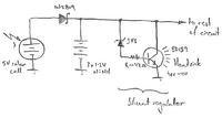
What you describe is certainly the *elegant* way to do it. Given the low power levels involved, there is a quicker, dirtier (and cheaper!) option though - you can simply connect the solar cell in parallel with the batteries and use a shunt regulator to dump the excess (solar) power when the batteries are full.

I've drawn a quick sketch...


Note that none of the components are especially critical other than the power dissipation rating of the transistor. The way it works is as follows:
The diode on the input isolates the batteries from the solar panel, protecting against inadvertent reverse polarity, night-time leakage currents etc. A Schottky is used for minimum forward voltage drop when carrying the panels' rated output current.

The shunt regulator operates by turning the transistor on at voltages greater than the (zener+transistor Vbe) voltage drop. At battery voltages below this level, the transistor is turned off. As the battery voltage starts to cross this threshold (when the panel's illuminated, and as the batteries approach being fully charged), the zener begins to conduct current from the rail through the current limiting resistor and into the base-emitter junction. Consequently the transistor's collector begins to sink current from the rail, which causes the rail voltage to drop. Further rises in battery voltage turn the transistor on harder, causing it to sink more current from the rail. For the values shown, the equilibrium (regulated) battery value will be approximately 3.3 + 0.7 =~ 4.0 volts.

Since the battery terminal voltage is less than this value, the regulator will cease sinking current when the solar cell is dark and therefore won't contribute to draining the battery overnight.

The downsides to this approach are:
1. The batteries are being maintained by an (approximation to a...) constant-voltage charging arrangement, which isn't ideal for ultimate battery life. Provided you don't set the regulator voltage too high (and ~1.3-1.5V/cell is pretty safe), I wouldn't expect this to be of any practical significance. If the maximum solar panel current is less than 1C (the battery capacity in mAh) - which at 700 mA is OK for any NiMH batteries larger than (and including) AAAs - this is fine.
2. The shunt regulator will dissipate the entire solar panel output as heat when the batteries are full. In your case this is only ~3.5 W, which can easily be achieved by bolting the transistor to a suitable heatsink (or probably even the side of a diecast box).
3. The voltage regulation of this circuit will be fairly poor, and will be a function of temperature and of the particular zener (and to a lesser extent the transistor) you use. For the intended application though, this really doesn't matter! This is one of those wonderful examples of the 'simplest circuit that will do the job' :) You might need to tweak the zener voltage to suit your particular need (zener characteristics at such low values of Vz are notoriously woeful!)


Enjoy!
 
Last edited:
thylacine1975,

this wont get it to do exactly what i want it to though, correct?

one of the key features im looking for is that it will stop recharging the batteries once the upper voltage is reached, say 4V, and recharging wont start again until the batteries have been drained to ~2V.
 

Mmm. Sort of...!

While it won't "start charging" at ~2V - it'll charge the batteries as soon as they have any capacity available to be filled. Generally, this is desirable in solar powered installations, since it stores all the possible solar power that is available to be stored, to maximise the system's capability to survive an extended dark period. There is no point in letting the batteries discharge to a 'start charging' threshold while there's (free) solar power otherwise available, only to have them go flat during the next cloudy day.

(This also avoids continual battery cycling. While this is [arguably] desirable to some extent in NiCd chemistry cells - all batteries suffer reduced capacity with continual cycling, becoming useless beyond 100's - 1000's of cycles)

Charging automatically 'stops' when the batteries' voltage reaches the regulated rail voltage of ~4V, as at this point they cease drawing current. Thus, while there's no clearly defined "charging" and "not charging" states of the above circuit, it will certainly keep the batteries as full as is possible from the available sunlight.

The nice extra feature a circuit like this provides is the ability for the load to continue to draw power at all times, with the shunt regulator only dissipating the difference between (input) solar power and (output) load power. i.e. as the load consumes more power, the shunt regulator dissipates progressively less until it reaches the point at which it is sinking zero current. At this point, the solar panel supplies the load (and any required battery charging current) directly as if the shunt wasn't there. If the load increases further, the batteries start contributing. Conversely, if the load decreases, the shunt again consumes the excess available photocurrent. [Incidentally, the shunt regulator also guarantees the voltage applied to the load is capped at 4 V, possibly easing the design of the power supply within the load.]

I hope that fills in some of the blanks. Oh, and that an autonomous solar regulator was really what you were looking for! :)
 
Ah! I see now. And i like it! Its all becoming oh so clear...

Could you perhaps explain how you came to the value of 47ohms for the resistor within the shunt regulator? also, what is the 3V3 component drawn in there? Lastly, what is Hfe ~ 100 stand for?

Thanks again for all the help!
 

The answers to these questions are all interlinked, so bear with me as I explain...

The 3V3 component is a zener diode, with a breakdown voltage Vz = 3.3 V (using the units - "V" in this case - in place of the decimal point is often done to preserve readability of the text on poor copies). Wikipedia explains these devices well (Zener diode - Wikipedia, the free encyclopedia). Here, we exploit the fact that at voltages BELOW Vz it conducts negligible current, while at voltages ABOVE Vz, it conducts (increasing amounts of) current. It serves to impose a voltage "threshold" at which the regulation action commences.

It's value (3.3 V) is less than the desired 4.0 V by another threshold lurking within the circuit - the Vbe (read as: Voltage across the base/emitter) of the transistor. [Strictly speaking, Vbe is not a constant, but a function of temperature and emitter current]. These effects can be neglected here [because a. the batteries won't care about slight voltage variations, and b. the horrible temperature dependancies of the 3.3 V zener will swamp the transistor parameter variations!] - indeed, for the majority of paractical cases it can be assumed to be constant of ~0.6 - 0.7 V. This voltage has to be developed at the base of our transistor in order for it to commence conducting collector current and exerting its regulating influence. Consequently, the sum of Vz + Vbe = ~4.0 V (in our case) defines the point at which regulation starts.

Once zener current (= transistor base current) starts to flow, the transistor will commence sinking substantially greater current via it's collector. The reason for "substantially greater" is due to the current gain of the transistor - the collector current is hfe * the base (zener) current. Hence for a BD139 with an hfe of ~100 (device dependant), the transistor would be able to sink the entire 700 mA of solar panel current with only ~7 mA of base (zener) current.

Let me emphasise that this way of thinking about a transistor (especially in a 'power' application such as this) is very much an approximation! I say this because while this level of analysis is entirely adequate for a small shunt regulator, I don't want you to feel that you can apply this model to all transistor applications. hfe (often interchangebly referred to as \beta) is a poorly controlled parameter in transistor manufacture and absent entirely from the more rigorous DC transistor models (such as Ebers-Moll). While it is a sensitive function of collector current (often shown on datasheets) and will vary substantially in this application, it is a valid way of visualising the transistor's operation here. It also allows for a simple design 'sanity check' in ensuring you can provide enough base current to sink the maximum expected collector current for the poorest (= lowest hfe) device.

This actually leads us to the 47 ohm resistor! It's job is to limit the base current to non-destructive levels in the event of excessive zener current. In this application it's not strictly necessary, but it'll protect the transistor's base (and zener) from the low output impedance batteries in the event the zener diode is inserted backwards ... it won't stop the transistor becoming furiously hot though :) The upper bound on its value is determined by the requirement that it pass the worst case base current (discussed above) without excessive voltage drop (which will otherwise affect the regulated output voltage). One of the (undesirable) characteristics of low voltage (such as 3V3) zener diodes is large values of (zener current dependant) series resistance, which will vary from (typically) 10 - 1000 ohms, effectively swamping this value for the expected range of currents.

I hope that sheds some light and/or offers a starting point for you to explore a little further... my apologies for the novel! As you can see, even the simplest circuits have many subtleties and approximations are often made to simplify analysis and design. It's remarkable what just a few components can do for you :)

Good luck!
 
thylacine1975, so ive made some progress on the circuit you have drawn out and explained. great explanation by the way! that was incredibly helpful.

although, i was looking at the drawing today and it hit me. if 5V is the output of the solar panel on a sunny day, and since the solar panel, batteries, and shunt regulator are all hooked up in parallel, wouldn't 5V be read at the start of the shunt regulator? 5V would be greater than the 3.3V diode, allowing current to flow through it, at which point current could then flow and get dumped into the BD139...

Am i thinking of this correct?
 

Heya Swimfan,

What a coincidence! I was only thinking of posting a correction/update back to this thread today having recently learned something about just how truly horrible low voltage zeners were! Most timely :)

To answer your question though, no - it's all OK. Because everything's connected in *parallel*, the same voltage is seen by everything simultaneously. Thus while your solar panel might be producing 5V by itself, when it's connected to the batteries, its terminal voltage will be 'dragged down' (loaded) by the lower voltage of the batteries. The shunt regulator will only start consuming current when the combined voltage of the two exceeds its threshold, corresponding to the batteries being fully charged. Schematic order isn't important at all.

Just on the shunt regulator itself, here's a revised schematic:


All that's happened is the diode has moved and we've added an extra resistor. Let me explain why:
I've been involved in another thread (https://www.edaboard.com/threads/239596/) where I proposed a similar configuration to terminate the charge cycle for a (mains-powered?) battery charger. In fact, you'll recognise much of the discussion :) While we were chatting, the chap involved prototyped the charger and reported behaviour traced back to poorly defined zener thresholds. The fix was to add the 470R resistor shown in the above sketch, to use the transistor's Vbe threshold to improve the threshold accuracy. The downside of doing this in your application is that the zener leakage/conduction current when Vz is so close to your battery voltage is likely to be non-neglibible, and will contribute to (very slowly) discharging the batteries.

Moving the diode will prevent this, by stopping the batteries discharging into either the panel or the regulator. The consequence of the diode move is that the battery voltages will appear ~0.4V higher from the perspective of the shunt regulator though, so the zener value should be increased correspondingly for the same level of regulation to be achieved. This has the added bonus of using a higher voltage (= marginally better) zener!

[I also suspect that your situation will be better off than the mains charger chaps' anyway, because of the higher collector currents (and also likely lower transistor gain) in your application.]

Let me know how it goes... oh, and don't forget to heatsink the transistor, or it *will* let the smoke out ;)
 
ahh, okay i see.

just to double check, I have introduced a means of limiting the current coming out of the solar cell, and have brought it down to a fixed output curent of ~270mA, which will flow right into the regulator. would this change any of the resistor values? or would everything stay roughly the same?

also, would you have any recommendations for the power rating for the resistors in the shunt regulator? due to current limiting, there will be a drop in the voltage seen at the beginning of the shunt regulator (~3.2V worst case scenario).


thanks so much for the help! :D
 
Last edited:

Status
Not open for further replies.

Part and Inventory Search

Welcome to EDABoard.com

Sponsor

Back
Top