Continue to Site

Welcome to EDAboard.com

Welcome to our site! EDAboard.com is an international Electronics Discussion Forum focused on EDA software, circuits, schematics, books, theory, papers, asic, pld, 8051, DSP, Network, RF, Analog Design, PCB, Service Manuals... and a whole lot more! To participate you need to register. Registration is free. Click here to register now.

Highest voltage output for Phase Shift Full Bridge?

Status
Not open for further replies.

cupoftea

Advanced Member level 5
Joined
Jun 13, 2021
Messages
2,802
Helped
55
Reputation
110
Reaction score
120
Trophy points
63
Activity points
14,785
Hi,
Do you know how high in output voltage that PSFB's usually go to? (1kW power level)
Vin is 240VAC mains ultimately..then Boost PFC, so 400VDC is input.

What is that voltage and power level where diode/capacitor multipiers are pretty much necessitated?
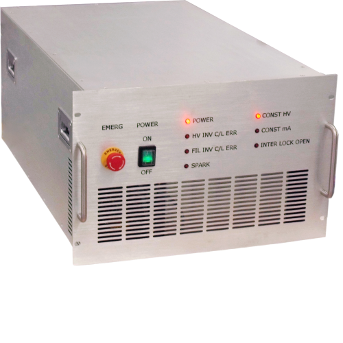
 

Thanks , its like this.. (but ours is single phase input)


...It uses a "High power resonant inverter"....so at some point, the LLC (or whatever), hands over to the Diode/Cap multiplier?

It seems that IGBTs and FETs etc, can only get up to 1200V or so, due to their ratings limits.
So after that, its voltage multipliers (Capacitor/diode)?
--- Updated ---

...In other words, have like a PSFB stage, but instead of the normal diode bridge output....you then have the AC innput to the Cap/Diode multiplier?...ditton with Pushpull smps, and LLC, etc etc?
 
Last edited:

Though radar tube power supplies use LLC's to give the 15kV directly...so there must be a way to get this. You can buy diodes rated to 96kV...so you can just rectify high voltage secondary with them.
Does anyone know of 1kV+ output power supply application notes?
 
Last edited:

This is specialised transformer design, often with many transformers and the sec's section wound on each - then a careful choice of diodes and volts per section to get to 60kV say, keeping capacitance down on the wdgs is one of the keys to success - as is the section winding.

The reason these supplies are resonant is to get a sine wave in volts on the pri & sec to make life easier for the diodes - sine current too . . then pot in a semi fluid silicon gel
 
Thanks, i would imagine that due to the clearances and expansiveness of HV SMPS's, (AYK, even though they are resonant there are still jagged bits on parts of the waveforms)...it is probably all but impossible to get HV SMPS through standard Radiated EMC approvals testing?
Consider eg a 1kV, 1kW Cockroft Walton....the size of the circuit and the jagged high di/dt currents over that big circuit......a gauranteed Radiated immunity fail every time i would have thought?.

...but the applications of HV SMPS in eg water treatment, xrays, radar, etc etc, are so crucial to society that we accept and just live with these Radiated EMC failures?

The attached is a 1kV 1kW Cockroft Walton, and looking at the current waveforms throughout it, you can say it would never pass Radiated EMC? (Unless locked away in a gasketted metal enclosure of some kind?
 

Attachments

  • COCKROFT WALTON.jpg
    COCKROFT WALTON.jpg
    274.6 KB · Views: 115
  • COCKROFT WALTON.zip
    2.8 KB · Views: 98
Last edited:

Cockcroft-Walton multiplier. Supply is mains 230 VAC. 4 symmetrical stages provide 1 kV to 1 kOhm load. No high frequencies are present.

Simulation is modified from a negative multiplier, therefore reverse diode directions to obtain positive polarity.

I omitted the two input capacitors although I observe wider voltage disparities within the circuit.
The 33 mH choke isn't absolutely necessary although including it results in closer alignment of supply voltage waveform with current waveform.

Cockcroft-Walton 4 stage bipolar 230VAC supply -1100VDC 1kW to load.png
 
I would imagine that due to the clearances and expansiveness of HV SMPS's, (AYK, even though they are resonant there are still jagged bits on parts of the waveforms)...it is probably all but impossible to get HV SMPS through standard Radiated EMC approvals testing?

I cannot imagine where you get such information from - perhaps you can enlighten us ?

If you have a sine wave on the drive to a Tx - you can usually be sure there are sine waves on the output side too ...

further - why use a voltage multiplier when you really don't need to - the dynamics of the control loop can be much faster without.
 
I cannot imagine where you get such information from - perhaps you can enlighten us ?
Just that it wil be harder to get a HV supply through Radiated EMC than a low voltage one of the same power...since the HV one needs more spacing and so is bigger, and you cant get "Go" and "return" tracks as close to each other with HV supplies.....so you get more of the loop antenna effect. As you know, with LLC, you get the "jagged bit" where the magnetising current juts out from the sine current shape. Also, the LLC switching nodes have high dv/dt. In HV supplies, as you know, the componentry is usually bigger and more spaced, so you unfortunately end up with more highly radiative "antennas" on the PCB......not to mention that HV components are rare things, and so have not had the "size reduction" emphasis of low voltage components..
 

I wonder with a 8kW , 60kV converter (240VAC in), its best to have 4 Boost PFCs each feeding a 2kW LLC with 15kV output...then stack the 4 outputs to get 60kV....or to have say a dual primary 4kW LLC...and stack its two 15kV secondaries....to give 30kV...then duplicate that, and stack, to get the 60kV?

I am sure you would agree that PSFB's are totally out of the question with outputs of 15kV.....and it has to be LLC or similar?

As you know , its standard precedure to have a "Buck" after the PFC, so that you can vary the buck vout, and thus vary the open loop LLCs output voltage (the LLC is fed by the buck)
 

As you know, with LLC, you get the "jagged bit" where the magnetising current juts out from the sine current shape. Also, the LLC switching nodes have high dv/dt

You are making more assumptions there - also you are limiting your argument to LLC.

The magnetising current is not seen on the output side, only the lower voltage driving side

Switching nodes do not have to have high dv/dt - that is purely the prerogative of the designer - and again this is only on the driving side - the LV side - comparatively.

PSFB could easily be used ( we have seen it as the driving source for 100kV psu ) but, again, the power circuit should result in sine waves to the rectifiers, and the driving stage should be designed for moderate volt transition slopes - which is easily done ...
 
Switching nodes do not have to have high dv/dt - that is purely the prerogative of the designer - and again this is only on the driving side - the LV side - comparatively.
Thanks, the attached LTspice shows a 15kv, 2kw LLC. Vin = 390v, f.upper = 50kHz.
Dead time 300ns.
The sec side switching nodes are going zero to 15kv in a few hundred nanoseconds.
It seems that it will be an interesting job to try and reduce this significantly.

AYK, that switching node will be made by a big high voltage diode, or lots of small diodes in series....making a big overall switching node area it seems....and the greater EMC challanges that this brings.

PSFB could easily be used ( we have seen it as the driving source for 100kV psu ) but, again, the power circuit should result in sine waves to the rectifiers, and the driving stage should be designed for moderate volt transition slopes - which is easily done ...
Thanks, it sounds like you are speaking about a PSFB thats been very heavily modified such that its more like some kind of hybrid converter....The "standard" PSFB would give overvoltage spikes on its output diodes, which are already suffering enough from the output voltage itself. This is why we woudlnt choose the "standard" PSFB for HV outputs like 15kV or so.
 

Attachments

  • LLC 2kW 15kV.jpg
    LLC 2kW 15kV.jpg
    185.9 KB · Views: 109
  • HalfbridgeLLC_50khz__15kV.zip
    2.1 KB · Views: 111
Last edited:

The attached shows a PSFB, (LT sim and jpg) with primary side diodes to the rail, and also turn off snubbers.....and includes a high leakage L, since AYK, thats what you end up with in high voltage output txformers.....so the sec diodes have high ringing voltage on them...and the voltage in the txformer, from the high L leakage, is very high, so we would rule out PSFB for high voltage outputs.
 

Attachments

  • PSFB ringing.jpg
    PSFB ringing.jpg
    129.6 KB · Views: 119
  • PSFB_with unipolar CST1_FWMout_test.zip
    3.2 KB · Views: 108

Apologies - as said in my post -

again, the power circuit should result in sine waves to the rectifiers, and the driving stage should be designed for moderate volt transition slopes
this may be outside your experience to date.
 
Thankyou, you appear to be alluring to "special" SMPS's that you have probably worked on that have low dv/dt at the switching nodes.
Yes, i am not aware of these. Though I am sure you aware that this topic would be of extreme interest to a great many.....

...AYK, None of the "standard" SMPS's have slow dv/dt of the switching nodes. You can slow it up a bit with turn-OFF snubbers etc, but not that much...not really significantly.
AYK, the "standard" LLC converter has high dv/dt on the primary and secondary switching nodes. IMHO, to make these dv/dt's significantly slower, would mean modification such that it wasnt an "LLC" any more.

...AYK, in an LLC, you have the "dead time" between the switching FETs.....AYK, this isnt much time.....the bus must be transitioned totally within this time, otherwise there wont be zero voltage turn on of the opposite FET in the leg......so a really slow dv/dt would be counter-productive there.

IMHO, I would call the "standard" SMPS's....
Buck, Boost, BuckBoost, SEPIC, Cuk, Flyback, 2Tran Forward, Half Bridge, Full Bridge, Pushpull, LLC, LCC, Series resonant converter, Active clamp forward, Phase shift full bridge, Asymetric Half Bridge.

....Also, am aware of hybrid converters, which are a mixture of the above. Also aware of the "Pe17" converter by Atal.
-Not aware of any others, and not heard of any with significantly slow dv/dt switching nodes.
 
Last edited:

Status
Not open for further replies.

Part and Inventory Search

Welcome to EDABoard.com

Sponsor

Back
Top