Continue to Site

Welcome to EDAboard.com

Welcome to our site! EDAboard.com is an international Electronics Discussion Forum focused on EDA software, circuits, schematics, books, theory, papers, asic, pld, 8051, DSP, Network, RF, Analog Design, PCB, Service Manuals... and a whole lot more! To participate you need to register. Registration is free. Click here to register now.

High Voltage RF 0-6MHz generator

Status
Not open for further replies.

Max-dal

Newbie level 4
Joined
Dec 15, 2010
Messages
6
Helped
1
Reputation
2
Reaction score
1
Trophy points
1,283
Activity points
1,332
Hi all,

I have a problem with my construction of an RF generator. The range can be fixed or variable, sine wave (2x, 180deg phase shift), output 100-400V, frequency 1-6MHz. The problem is, that I am able to use an RC circuit to generate the required voltage and amplitude but I need to have two sine waves with a phase shift of exactly 180deg.

Now I've got the problem how to synchronise the two waveforms from two sources or use one source with two outputs (transformer)..., got stuck:-?.

I will appreciate any good ideas.:wink:

Peter.
 

do you really have to go down to DC?

Use two op amps, one with gain of 1, the other with gain of -1. If they are broadband, the phase shift will be 180 degrees +/- a few degrees. Those op amps drive your high voltage output circuits independently, but are driven by the same source frequency.
 

Hi biff44,

thanks for the good idea. The frequency does not have to be 0, actually minimum is about 400kHz. I've been thinking how to use op amps, but the solution seems rather difficult. The high voltage op amps are expensive and are unable to reach frequency >30kHz (see the attachment for Cirrus Logic PA241) at 280Vp-p, although the bandwidth is declared to be 3MHz but not at such a high voltage. Thermal loses are also excessive.

Perhaps to select a suitable op amp to gain current instead of voltage and drive a tranformer with ratio, for example, 1:20 ?
 

Attachments

  • PA241U_I.pdf
    701.5 KB · Views: 45
Last edited:

Obviously, your present description is too vague to understand what you already have and possibly need in addition. You should start to describe the present design exactly. Otherwise, it's just jumping into conclusions.
 

Hi FvM,

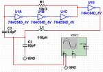
right now, I have only a few conceps of the working device. Basically only two. The first is an op amp construction fed by a signal generator and producing waveforms for an RF ion focusing device (capacitive load). However the op amps are quite lossy. The second one is a free running resonator circuit made by simple NOT gates producing square-wave signal which would excite a high quality RC resonator circuit producing a high RF voltage. The frequency could be changed only by replacing the resonator components but that's not an issue. I simulated this device, the circuitry is shown in the picture below.
Resonator.JPG

The problem I need to solve is production of two waveforms of the same frequency and voltage but shifted about 180deg with respect to each other.
 

a high quality RC resonator
means LC resonator, obviously. Unfortunately, you have to consider real component properties, particularly L losses. I believe, that a high Q circuit can achieve considerable voltage multiplication factors, but hardly exact 180 degree phase matching, unless it's designed as a symmetrical resonator structure from the start. Because this is pure electronic design craftsmanship, general suggestions won't help much.

If the design is dedicated to a state-of-the-art scientific instrument, digital controlled signal generation and stable HV amplifiers utilizing feedback would be the means of choice.
 

Better than using gates is to use the Q outputs of a D-type flip-flop 7474. You get division by 2 also, but the phase difference is much accurate.
The Q outputs can drive two high-voltage transistors and use low-pass filters at the output for shaping the waveforms.
 

I would suggest hiring a qualified consultant to design this for you. The tough part is, obviously, the 400 V output circuits, and figuring out your actual load requirements. How to generate two out of phase .4 to 6 MHz signals is a trivial design task for any RF consultant.

I would start off looking for a 500 Vds mosfet that can handle the frequency range with gain, and build two simple single stage inverting transistor amplifier circuits. You drive it with the two op amp circuits. You can generate the signal with a signal generator chip, maybe a 555 timer chip, or a DDS chip if you want to be precise.
 

Thank you all for your fresh ideas :wink:
 
  • Like
Reactions: goal

    goal

    Points: 2
    Helpful Answer Positive Rating
Status
Not open for further replies.

Part and Inventory Search

Welcome to EDABoard.com

Sponsor

Back
Top