Continue to Site

Welcome to EDAboard.com

Welcome to our site! EDAboard.com is an international Electronics Discussion Forum focused on EDA software, circuits, schematics, books, theory, papers, asic, pld, 8051, DSP, Network, RF, Analog Design, PCB, Service Manuals... and a whole lot more! To participate you need to register. Registration is free. Click here to register now.

High Voltage DC Buck Converter

Status
Not open for further replies.

mjasoj

Junior Member level 2
Joined
Nov 9, 2012
Messages
21
Helped
2
Reputation
4
Reaction score
2
Trophy points
1,283
Visit site
Activity points
1,423
Hello All,

I am struck in my FYP High Voltage DC Buck Converter. I have to design a buck converter capable of producing 300VDC at an input of 4000 V DC. I was thinking of single switch isolated Flyback converter.
IXTA 02N450HV MOSFET can be used as a switch capable of handling 4500V & 200mA
Any suggestions? Would it be practically possible or not?
 

I have not worked with 4,000 V but I have worked with 1,000 V which was going through a transformer winding. It is very easy for arcing to occur among the windings. (I found this out after storing the unit in a humid basement.) Once arcing has started, it tends to stay. I had to replace the transformer. Fortunately a plain transformer can withstand 1,000 V.

But as for 4,000 V, that is a high enough voltage that it can jump small gaps.

I believe you'll need a special type of enamel on your wire, to insulate your windings carrying 4,000 V.

Furthermore, remember an inductor can generate a high voltage spike, when you shut off current through it.
 

I think getting enough inductance will be a problem. As said, the windings should be divided to reduce the voltage across across any layer to < 400V and a couple of layers of mylar tape wound over each layer or wound on a multisection bobbin with the same idea in mind. It is difficult to get the wire from one section where its on the outside back into the inside of the next section without an air gap and two insulating "washers" (suitablely sealed to bobbin).
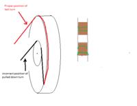
LOPTs use a very thin(1/4" -> 1/2") and deep (> 1" depth) winding which was totally encapsulated( to keep the winding mechanically sound) to give them the >10KV voltage output, but it was still the least reliable part of an old CRT based TV/monitor. I suppose that you could get a bobbin made and as you wind, soak the windings in polyurathane varnish, which will help to exclude water, but I think you will still need some tape in to stop any turns being pulled down to a layer nearer the core, so at the worst case you have the inner turns at 4KV and a "pulled down" turn which should be on the outside at 300V.
Frank
 

Sounds rather demanding for a FYP because both switched mode supply and high voltage experience is needed. I presume you are talking about a real design, not just paperwork (a concept study).

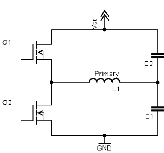
The suggested half bridge topology is clearly preferable because it halves the AC voltage magnitude. Operating a 4.5kV transistor at 4 kV bus voltage is still a small margin, may be too small.
 
  • Like
Reactions: mjasoj

    mjasoj

    Points: 2
    Helpful Answer Positive Rating
Thanks All for your great ideas shared with me.

I think getting enough inductance will be a problem. As said, the windings should be divided to reduce the voltage across across any layer to < 400V and a couple of layers of mylar tape wound over each layer or wound on a multisection bobbin with the same idea in mind. It is difficult to get the wire from one section where its on the outside back into the inside of the next section without an air gap and two insulating "washers" (suitablely sealed to bobbin).
LOPTs use a very thin(1/4" -> 1/2") and deep (> 1" depth) winding which was totally encapsulated( to keep the winding mechanically sound) to give them the >10KV voltage output, but it was still the least reliable part of an old CRT based TV/monitor. I suppose that you could get a bobbin made and as you wind, soak the windings in polyurathane varnish, which will help to exclude water, but I think you will still need some tape in to stop any turns being pulled down to a layer nearer the core, so at the worst case you have the inner turns at 4KV and a "pulled down" turn which should be on the outside at 300V.
Frank

Thanks chuckey for your great idea for the winding of transformer. One thing i would like to ask, soaking the windings in polyurathane varnish, the innermost layer is wound after some taping to properly insulate from the core and windings make a sandwich of mylar tape between with some additional thin paper sheet. Isn't it enough for 4kV ??
Is pulled down turn necessary for this? Can you please elaborate your this idea onto a piece of paper and post it here in the form of an image that how can i do that practically? Thanks alot in advance.

Sounds rather demanding for a FYP because both switched mode supply and high voltage experience is needed. I presume you are talking about a real design, not just paperwork (a concept study).

The suggested half bridge topology is clearly preferable because it halves the AC voltage magnitude. Operating a 4.5kV transistor at 4 kV bus voltage is still a small margin, may be too small.

FVM, Thanks as always! I know its greater than a simple FYP, but i'm literally stuck in it and don't know the way to go out, i have one month to show it as a real design, exactly it is not a paperwork. I think you are talking about a Push-Pull Configuration using a center-tapped transformer. Also you stated that Half Bridge Topology halves the AC Voltage Magnitude but still VDS of the Mosfet in this configuration wouldn't be 4kV, like in single switch configuration? Thanks in Advance
 

This is the sort of thing I meant - .
The way profesional LOPTs are wound is "pie" wound, so the structure is self supporting to a certain degree. If you look at a solenoid wound coil, the turns are parallel to each other, in pie wound coils the turns are wave wound, that is as you look at the coil, each turn has a sinewave form. So at a certain point the wire will be on one edge of the coil then is crosses the coil and runs along the other edge then it crosses back. The amount of side to side deviation gives you the width of the coil but it is important that the on sucessive turns that the wire position slips by the diameter of the wire else any turn would try and sit on top of the previous turn and the structure would be unstable. This method of winding reduces the parasitic capacity in the coil. Old fashioned RF coils were wound like this, like the long wave coil on a ferrite rod aerial or IF transformers. You need a proper coil winding machine to make these sorts of coils and the knowledge to set the gear ratio correctly to get the right side to side wave shape of the windings.
Frank
 

Also you stated that Half Bridge Topology halves the AC Voltage Magnitude but still VDS of the Mosfet in this configuration wouldn't be 4kV, like in single switch configuration?
Yes 4kV, compared to 8kV (double Vin) or similar in single switch topology.
 

Thanks chuckey for great explanation through diagram, i understood your idea more clearly.
If you don't mind, one other thing, can i wind this transformer on E-I type core? Because i have an experience on that previously?
If yes, what are required precautions?
If no, what could be maximum voltage value for which i can use this core type?

FvM, But for Half Bridge Topology, i would have to wind twice of Vin. Means 4kV-0-4kV Winding on primary. It would become a headache for me.. :(
Any other idea which could support single switch topology.. plz?
 

LOPTs are normally wound on a square core, with the primary on one limb and the secondary on the opposite one. This is to get the spacing between the very deep EHT winding and the primary. With an E I core I think the preferred layout is to have the primary and secondary side by side on the centre limb - with a good piece of insulation between them - secondary on a bobbin with one thick wall?. Another way would be to wind the primary on the centre limb and split the secondary into two windings one on each outer limb. This way the depth of the each secondary would be reduced, so to increase the air gap to the primary.
Frank
 

But for Half Bridge Topology, i would have to wind twice of Vin. Means 4kV-0-4kV Winding on primary.

??? In my understanding a half-bridge uses a topology like below. I'm sure Orson Cart meaned the same in post #3

4409001900_1420983057.png
 
Status
Not open for further replies.

Part and Inventory Search

Welcome to EDABoard.com

Sponsor

Back
Top