reeddreed
Junior Member level 1
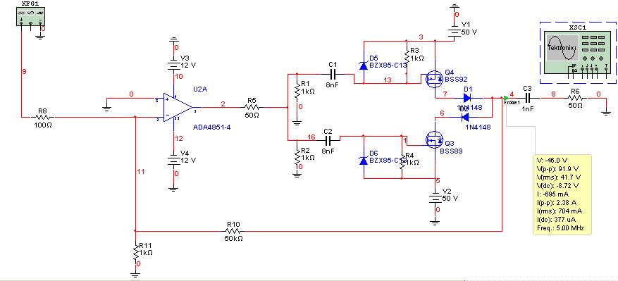
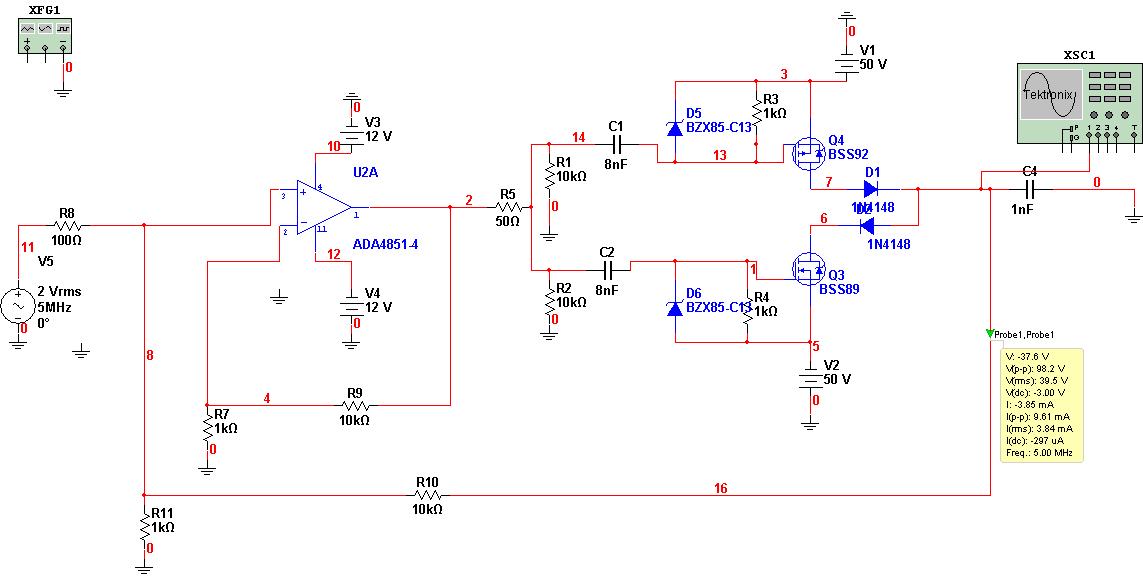
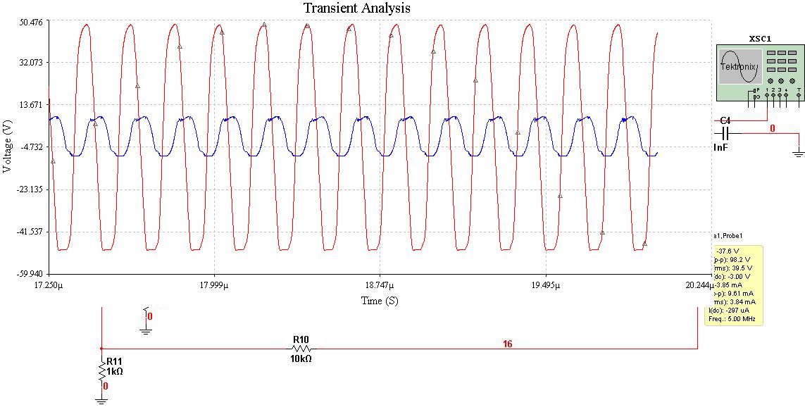
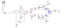
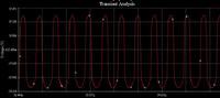
Hey, I did so here is layout now ... I added a high-speed operational amplifier ...
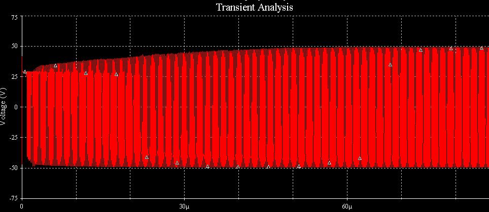
the input signal is 5 MHz sine wave 2 Vpp
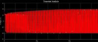
problem is the slow growth of the signal up to 100 Vp
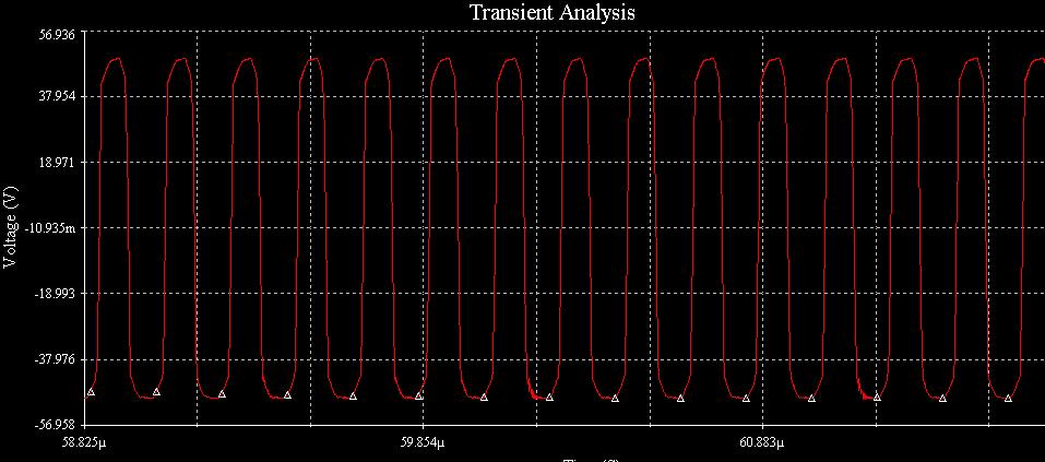
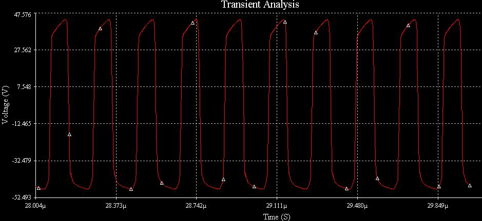
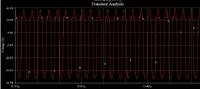
underneath the chart of simulation
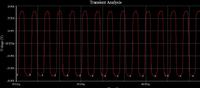
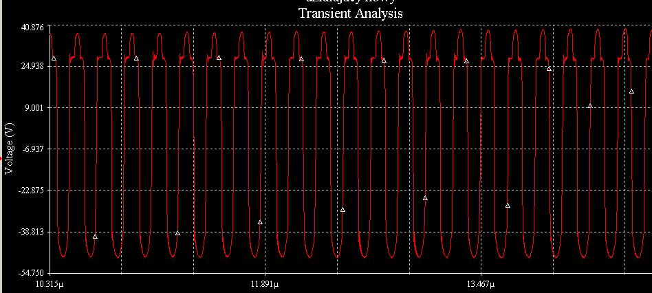
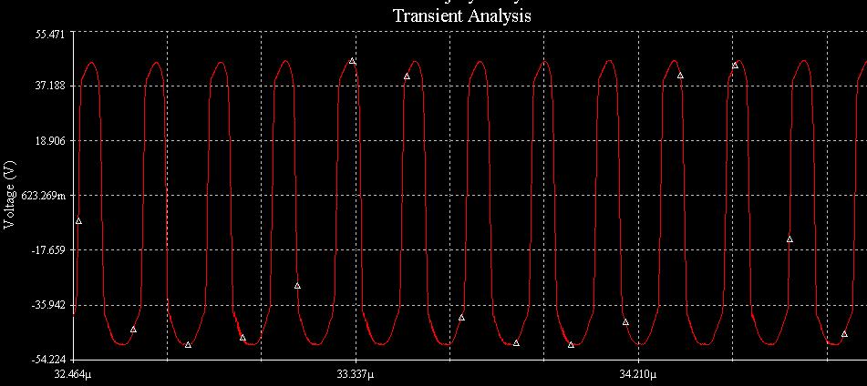
the input signal is 5 MHz sine wave 2 Vpp
problem is the slow growth of the signal up to 100 Vp
underneath the chart of simulation