Continue to Site

Welcome to EDAboard.com

Welcome to our site! EDAboard.com is an international Electronics Discussion Forum focused on EDA software, circuits, schematics, books, theory, papers, asic, pld, 8051, DSP, Network, RF, Analog Design, PCB, Service Manuals... and a whole lot more! To participate you need to register. Registration is free. Click here to register now.

High voltage amplifier and high frequency

Status
Not open for further replies.

reeddreed

Junior Member level 1
Joined
Nov 21, 2010
Messages
17
Helped
0
Reputation
0
Reaction score
0
Trophy points
1,281
Activity points
1,409
Hi
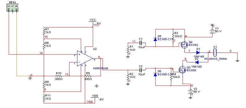
This project is a high voltage amplifier to the piezo transducer
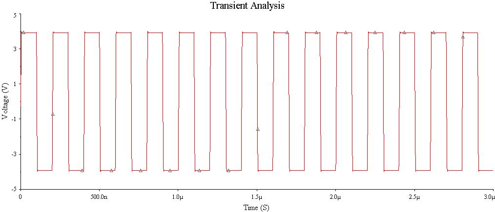
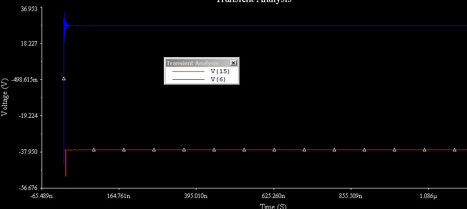
4 Vpp , frequency 5MHz, output signal 90 Vpp

I have him perform a degree of control that will enter the system unbalanced signal.
I have no idea how I can do this, I thought about doing something similar to the active di-box .. but if it is a good idea?
Please any help and ideas....:wink:

projekt wzmacniacza2.JPG
 

Maybe some other concept?:)

Sure. In principle, your concept isn't far from possibly working ;-).

However, if the "-" output of your XFG1 is a phase-inverted version of the "+" output -- which is to be suspected: when the "+" output is positive, the "-" output is negative against GND -- both transistors would be controlled "on" at the same time -- and immediately burn out, if there's no current limitation, of course. Hence one of the two XFG1 outputs would need a phase inversion.

If the phase control of both MOSFETs works correctly (no overlapping), the 2 diodes are dispensable, I think.

Last not least: Instead of the HC49 Xtal, you'd need of course a piezo transducer which can stand and emit such high power. But I guess you'd know this.
 

Of course, I agree with you ... the HC49 for Xtal I just wanted to simulate the load on the output of the amplifier.

I have a problem with this mainly to somehow control this amp ... I put the following curves transient, ac analysis
I wanted to do it on an operational amplifier ... so that this amp had some control of the transistors
As the chart shows, this sinus is flattened
Control by feedback? .. and phase inversion ... I do not know too much how to do it
 

As the chart shows, this sinus is flattened

Without your schematic, nobody can help you, I guess.

If you control both transistors by one or two highly amplified sine wave(s), most of the time both transistors will conduct, and a large cross current through both transistors will occur (changing them soon into black smoke :-( ).
Did you check the currents and/or power consumption of your sim. analysis?
 

I don't understand the purpose of the frequency response diagrams. You can either operate your circuit in switch mode, which would be basically possible at 5 MHz, although the switching transient will take a considerable part of the total period, or as a linear amplifier. For a switch mode output stage, AC analysis (=small signal) would be meaningless. A class AB linear amplifier would work, but has much higher losses. Because a resonant transducer is working as a bandpass, the current waveform will be almost sinusoial with a switch mode output stage. But it requires strong gate drivers to achieve fast switching and minimize losses.
 

I'm really not experienced in the design ... and this type of amplifiers is not popular.

Therefore, as you may have the schematic of such a device which could to control the amplifier ...
For now I would not worry about the loss of this amp ..

Have not checked the power losses and current
Sorry for the little specifics ... but I really have no experience.
 

... Because a resonant transducer is working as a bandpass, the current waveform will be almost sinusoidal with a switch mode output stage. But it requires strong gate drivers to achieve fast switching and minimize losses.

Hello FvM,

this triggered an idea: would it be possible to stimulate with a subharmonic? There are HV half-bridge drivers available, which should work up to 1MHz, s. the PDF below. They can drive loads of several nF's, support adjustable dead time, and drive two equal NMOSFETs.
View attachment LM5104_NS_halfBridge.pdf
 
Subharmonic drive is an interesting idea. but the spectral share of 5th harmonic is only 1/5 of the fundamental for a square wave (and getting absolutely smaller when reducing the duty cycle), so I fear, it won't lead to an effective design.

Driving MOSFETS to ns switching speed requires strong gate drivers with several A output current, usually discrete BJT push-pull stages are used. You would power them by auxilary supplies at both rails, because capacitive coupling isn't a goog idea at this high currents. Alternatively, a single class C output amplifier may be a solution, having higher losses, but can be better driven by a sine source. Refer to RF PA literature about the design.
 
This application will be able to act LM5104_NS_halfBridge.pdf
Only it needs a solution that I could perform in Multisim.

Your best bet would be to control the MOSFET with some of the operational amplifier with feedback.
Except that I do not know how such applications do

My project is based on the solution Supertex tc6320

**broken link removed**

Here is the module MD1213 ... I do not do something like this .. .. too much complexity and the likelihood that it will not work
 

My project is based on the solution Supertex tc6320

**broken link removed**
Here is the module MD1213 ...

I do not do something like this .. .. too much complexity and the likelihood that it will not work

This MD1213/TC6320 combination seems utterly appropriate for your application. If you don't want to build it yourself, you could use the MD1213 + TC6320 Demoboard - possibly available fully assembled, so the risk that it wouldn't work is rather minimized.

You'd need a 5MHz logic square wave drive with a slewRate ≤ 2ns. Because of the MD1213's good symmetry, probably both inputs could be driven in parallel.
 

I already thought of Supertex when I saw your circuit with the two diodes. There are two points to consider if you want to claim your circuit is "based on the Supertex example"
- You have to provide a sufficient gate drive current for fast switching, the Supertex chip e.g. supplies 2 A. You can use any usual gate driver IC or an equivalent solution of your own.
- You need to generate suitable non-overlapping control signals. Your Multisim circuit doesn't.
 

The TI gate driver is O.K. You surely don't need 10 uF coupling capacitors. And the waveform from the Multisim genrator still doesn't give a correct waveform, as before. As said, you should have squarewaves that achieve non-overlapping switching of the output transistors.
 

Only my professor told me to do this project for the sine signal ..
When I removed the capacitors, the amplifier has stopped working

The following simulation ... what wrong plug?


Hey
Recently trying to continue to make this control system

Something like the last time I tried to run


The output of this amplifier with a signal sine, 1 Vpp input gives about 7 V output
Of course, this is where the control system is not connected to the main circuit


When connected to one half circuit the output, unfortunately, nothing appears

What could be wrong?


I may want to copy the statement from my previous post :sad:

Seriously, I'm unable to locate the source of waveforms. The +/- 4V square wave may be the generator input. Node V(15) isn't existing in the schematic, so apparently the second plot is from a different circuit.

Apart from these doubts, shorting the input to the high-side driver can't result in any reasonable output. I also don't understand, why you use a clamping amplifier, set to +/- 2.5 V clamp level?
 
I have to give up this idea ... I talked with my professor and it is not something I needed .. and it will not work very well

Now I will try to connect to one input of inverting operational amplifier, and the second non-inverting
and try to achieve something with feedback

Will be best to use a wide-band amplifier?
 

Status
Not open for further replies.

Similar threads

Part and Inventory Search

Welcome to EDABoard.com

Sponsor

Back
Top