Continue to Site

Welcome to EDAboard.com

Welcome to our site! EDAboard.com is an international Electronics Discussion Forum focused on EDA software, circuits, schematics, books, theory, papers, asic, pld, 8051, DSP, Network, RF, Analog Design, PCB, Service Manuals... and a whole lot more! To participate you need to register. Registration is free. Click here to register now.

High frequency voltmeter attenuation

Status
Not open for further replies.

eckaman

Newbie level 3
Joined
Jan 4, 2012
Messages
3
Helped
0
Reputation
0
Reaction score
0
Trophy points
1,281
Activity points
1,310
Hi everyone,

I made a half wave rectifier with a single op amp and LED and made a filter with a cap and resistor as shown.
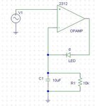
rectifier.JPG

At low frequencies this works without a problem. The DC voltage across the resistor and cap is exactly equal to the peak of the input signal. But at 50kHz, the voltage across the cap and resistor has been attenuated by something (pic below).
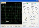
untitled2.JPG

This attenuation decreases for lower input voltage and lower frequency. I don't think it's a problem with the scope input impedance, because I'm measuring a DC signal. Unless the output impedance of my circuit increases with input voltage and frequency.

Does anyone know what is causing the drop?

Thanks!
 

You should read a textbook on basic electronics measurements.

In short, there are two problems: the frequency response of your operational amplifier, and second, loading the signal source by the circuit.

To reliable measure AC voltage, you should do it on a known source impedance, and your voltmeter should be matched to it. At higher frequencies, "a detector" becomes to have stray impedances added which should be taken into account.

Another approach was adopted by R&S many years ago: they designed an AC and RF voltmeter with a high-impedance detector which was designed to have a flat frequency response up to > 200 MHz.
At higher frequencies, voltage is no more a reliable quantity, so power sensors are preferred.
 

Thanks for the reply.

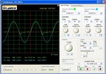
It doesn't seem like there is a frequency response issue with the op amp, because if I take the cap out the peak output of the rectifier is accurate.
new.JPG

But when I put it back in the rectified and filtered signal drops
newer.JPG

Would this mean that the input impedance of the op amp isn't the problem, or that adding the op amp affects the input impedance of the op amp?

Or does the cap affect the output impedance of the rectifier?
 

What makes you think that a LED is any good at rectifying AC at high frequencies. Also certainly it has a lot of shunt capacitance associated with it. Try a hot carrier diode, they are designed to a, be a rectifier and b, work at high frequencies.
Frank
 

An LED is I'm sure not great at rectifying really high frequencies, but as you can see in the image I posted it does work well enough at 50kHz. I know that the voltage drop across a LED is greater than the drop across a diode, but that is compensated for by the op amp. The problem doesn't come about because of the LED but when I attach the filter capacitor.

It seems that either the cap is creating too high of an output impedance or that it lowers the input impedance of the op amp. I calculate the impedance of a 10uF cap and 10k resistor in parallel to be about 0.318Ohm (almost entirely reactive). And since I've been using a voltmeter with an input impedance of 11MOhms to measure the voltage across the cap/resistor, it seems that the cap must be affecting the input impedance of the op amp.
 

The problem is the slew rate of the opamp. Suppose you LED has a shunt capacity of 400 PF. With no capacitor fitted the output stage of the op amp has to deliver current through the forward impedance of the diode shunted by 400 PF into a 10K resistor. When you place the capacitor in parallel, the output stage then has to charge the 10MF and 400 PF during the half cycle time of the input wave form, it can do this slowly up to 50KHZ but not at high speed. Hence it gets less sensitive at high frequencies. You could try and increase the value of the 10K and reduce the value of the 10MF. As I said its the capacitance of the LED that is the main trouble along with the slew rate of the opamp.
Frank
 
Status
Not open for further replies.

Part and Inventory Search

Welcome to EDABoard.com

Sponsor

Back
Top