Continue to Site

Welcome to EDAboard.com

Welcome to our site! EDAboard.com is an international Electronics Discussion Forum focused on EDA software, circuits, schematics, books, theory, papers, asic, pld, 8051, DSP, Network, RF, Analog Design, PCB, Service Manuals... and a whole lot more! To participate you need to register. Registration is free. Click here to register now.

High frequency FET for simple TV transmitter circuit

Status
Not open for further replies.

I14R10

Full Member level 3
Joined
May 31, 2015
Messages
185
Helped
0
Reputation
0
Reaction score
0
Trophy points
1,296
Activity points
2,750
I am planning to build this circuit


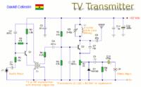
I've already built it before but I had limited success with it. Farthest that I could get it to transmit is around 10m-15m. I understand it's just an oscillator without power amplifier on output. The problem was poor performance of BC547 transistor at VHF. I am always trying to experiment with the circuit and I want to replace BJT with FET. Do you have any recommendation on what FET to use?

I have lots of BF244A https://www.futurlec.com/Transistors/BF244A.shtml FET's, but I don't know if they will be alright.
 

I think the diagram you show is quite primitive. The antenna will influence the transmitted frequency. It would be better to use a buffer transistor at the output of the oscillator (repeater on emitter maybe). I don't think you need to change from bipolar to FET. The TV spectrum is very large, from 48 MHz to over 800 MHz. What channel do you want to transmit on? For a short antenna, you should use higher frequencies. For lower frequencies, the antenna should be longer.
 

I understand it's just an oscillator without power amplifier on output.
It's actually two oscillators, T1 is generating the 5.5 MHz audio subcarrier.

BF244 can probably work with circuit modifications, but why not use a 1 - 5 GHz fT small signal RF transistor?
 

I think the diagram you show is quite primitive. The antenna will influence the transmitted frequency.

Yes. You can't come near the circuit or the antenna. Frequency drifts if you do that.
I want to transmit on lower VHF bands. Antenna length is not a problem.

FvM, can you recommend some small signal RF transistor?
 

I have one more question.
How do you calculate operating point when dealing with LC circuit in collector? Impedance of LC circuit at resonance approaches infinity. In that case load line is 0 for every point on graph. If it was a resistor it would be going from two points, Vcc on x axis towards Ic on y axis.
 
Last edited:

Does anybody has any advice on how to make this circuit more stable? I already added JFET buffer between collector and the antenna and one on video input. Last one was needed because I was getting distorted image just from touching the camera. Now I can touch the antenna and the camera without much distorting the image. But the next problem is that the image gets considerably distorted depending on the how the cables are positioned. If I have cable from supply and cable from camera (video input) close together and parallel then the image is fine. Otherwise image is completely distorted.

One more problem is, although it's not really a problem - I can't change frequency of the LC circuit. It's around 200 MHz. No matter how large or how small I add capacitor or inductor the frequency only changes by a small amount, from 150MHz to 210MHz.
 

Status
Not open for further replies.

Similar threads

Part and Inventory Search

Welcome to EDABoard.com

Sponsor

Back
Top