Continue to Site

Welcome to EDAboard.com

Welcome to our site! EDAboard.com is an international Electronics Discussion Forum focused on EDA software, circuits, schematics, books, theory, papers, asic, pld, 8051, DSP, Network, RF, Analog Design, PCB, Service Manuals... and a whole lot more! To participate you need to register. Registration is free. Click here to register now.

hfss or cst how to include a black box with specific s parameters in the whole design

Status
Not open for further replies.

tamer504

Newbie level 4
Joined
Oct 29, 2008
Messages
6
Helped
0
Reputation
0
Reaction score
0
Trophy points
1,281
Activity points
1,319
folks;
hi all
i have got an important thing to ask for both users of hfss and cst


i would like to simulate a real switch that connect 2 microstrip lines ,i already have the s parameters (s2p file for the switch),but i do not know how to do it,

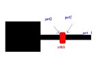
input port ----->>microstrip----switch data---another microstrip

my problem here is how to define the ports at both edge of the virtual switch block diagram (e.g at the end of the 1st microstrip and at the start of the second microstrip)
 

you can do it in AWR or ADS. do you need momentum analysis or just schematics simulation?
 

cheers tony
so there is no way i can do it with hfss or cst
 

You can do it in CST Design Studio. There you can choose a Touchstone file in the Block selection tree "Data import" and add it as a block. You can add other electric elements and also create a model around it.
 

cheers folks
ok that is fine ,,i had my switch block linked with the s parameter file ,but how to
link the ports of the box with the ports in the cst patch antenna microwave simulation.
in another words what i am really simulating is a patch antenna with a microstrip feed.i want to insert this switch into the feed ,please find attached an illustrative image .
 

Attachments

  • patch.JPG
    patch.JPG
    12.4 KB · Views: 206

if any one looked in the attached file there is port 2 and 3 which i do not know how to define in cst or hfss
 

1) The usual method is to simulate the EM part in the EM simulator, with ports for the components.
Then, all components and the EM blocks are combined in a circuit simulator like ADS, MWO etc. to give the "complete" result.

2) There are some EM simulators where you can insert subcircuit blocks into the EM model. This will give the same results as 1)
 

in MicroWave Studio you can add one port for your switch and one for the output. Then choose in Design Studio the option differential ports. So you can connect your switch at this differential port.
 

thx
are u suggesting that at both end of the microstrips edges at which the switch will physicaly touch ,i should define 2 discrete ports IN CST
 

I think you should try it with one port between the edges and connect the switch to this port.
 

2) There are some EM simulators where you can insert subcircuit blocks into the EM model. This will give the same results as 1)

Dear Volker,

I found your reply very interesting and I desire to know in which EM simulators you can insert a subcircuit blocks with assigned s-parameter.

Thank you for your attention
 

in which EM simulators you can insert a subcircuit blocks with assigned s-parameter.

Hello Miricol,

you can do that in Sonnet. There might be other simulators which can also include S-parameter blocks in the EM model.
 

in which EM simulators you can insert a subcircuit blocks with assigned s-parameter.
Hello Miricol,

You can do it in Ansoft Designer as well.

Best regards,
 
Status
Not open for further replies.

Part and Inventory Search

Welcome to EDABoard.com

Sponsor

Back
Top