Continue to Site

Welcome to EDAboard.com

Welcome to our site! EDAboard.com is an international Electronics Discussion Forum focused on EDA software, circuits, schematics, books, theory, papers, asic, pld, 8051, DSP, Network, RF, Analog Design, PCB, Service Manuals... and a whole lot more! To participate you need to register. Registration is free. Click here to register now.

[HFSS] Coax - Microstrip Transition

Status
Not open for further replies.

res

Newbie level 2
Joined
Sep 29, 2006
Messages
2
Helped
0
Reputation
0
Reaction score
0
Trophy points
1,281
Activity points
1,303
Hello,

I am trying to optimize an coax to microstrip transition using an SMA connector that is available to me. I have drawn up the connect within HFSS and have run many simulations using many different excitations and by experimenting with airbox size and so on. I do not have much experience with HFSS, but I believe the simulation as I have it now is setup correctly, yet I cannot obtain results which match those that I have measured from the VNA.

Can anyone provide me with any insight or ideas as to why I cannot get my simulation to match the results?

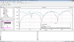
Attached I have a screen shot of my results and the simulation results, and the HFSS file of the simulation. Any help is appreciated.
 

Attachments

  • HFSS SMA.zip
    22.3 KB · Views: 198
  • Results.png
    Results.png
    74.1 KB · Views: 203

When you connect the SMA center pin to the microstrip, you need to leave a gap between the end of microstrip and SMA. Otherwise, the microstrip may be shorted to the ground. Also, you need to make the gap big enough, otherwise, it may couple to the end wall and degrade your VSWR.

Good luck!
 
Hello,
Both very excellent points that I had not considered. I will look into this as soon as possible.

UKnowWhat, did you make these cross sections yourself? I am aware that the dimensions of the center pin are very important, and may be able to dismantle one of the connectors I have to take a closer look. From the picture it looks like the connector has a silver/chrome appearance. The connectors I am using are gold plated, so perhaps the datasheet I am refering is slightly different. I believe I have an Emerson connector with p/n 142-0701-881. More importantly, it appears that in the narrow section of the center pin, the teflon has air gaps that may be difficult to model; is this correct?

I appreciate the help guys, this is very good.
 

No I didn't. Someone in the lab did it for me quite a while ago.
I don't think there is any air gap that is visually noticeable at the center and I just checked under microscope. The area is all filled with Teflon. It's hard to see in the picture but the 2 sections connected together by the narrow section at the center are all tapered out at the end.
 

Hello,

How / anyone has a diagram on how to do a connection from coax feed microstrip patch to an SMA connector?

Thanks in advance
 

Status
Not open for further replies.

Part and Inventory Search

Welcome to EDABoard.com

Sponsor

Back
Top