deepak007
Member level 5
hello
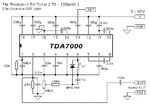
i want to modify a tda 7000 fm receiver. it has varactor diode tuning. can anybody help me to modify it to operate in the 130 to 150mhz region? i mean what value of inductance is to be used to change it to the desired frequency with out changing the varactor diode given in the schematic. because i have ordered that diode..or at least please tell me the principle and formula for varactor tuning.i donot know how to select varacor diode. is there any way to measure the capacitance of unknown varactor diode.
i am enclosing the schematic.please help me.