zsolt1
Full Member level 6
- Joined
- Aug 11, 2012
- Messages
- 367
- Helped
- 50
- Reputation
- 100
- Reaction score
- 49
- Trophy points
- 1,308
- Location
- Cluj-Napoca, Romania
- Activity points
- 3,880
HI,
how to get signal from BTL amp , in order to feed with signal an other amp (sub woofer with tone correction preamp) ?
There is no other signal source from first device which is a multimedia player in a Dacia Duster . Has only 4 speaker outputs in BTL connection . (It has an SPDIF output on the back , but is to much effort to work around that...)
Last edited:

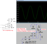
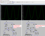
") what about 1 K for resistors and 1 uF for caps ?
what about 1 K for resistors and 1 uF for caps ?