jm2t
Newbie level 4

- Joined
- Oct 4, 2013
- Messages
- 6
- Helped
- 0
- Reputation
- 0
- Reaction score
- 0
- Trophy points
- 1
- Activity points
- 73
Hello edaboard, I'm new here and I'm sorry my first post has to be a question, but I am really desperate with this one.
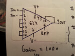
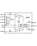
I've been working on a EKG amplifier using the AD624. You have the pin connection and schematics for a gain = 1000, extracted from the datasheet below.

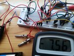
The big problem is, I connect everthing right, and the V output, when the two inputs are connected together (in theory, Vdif=0) keeps pointiong as -7,6V respect to ground. Not only that, but if I diosconnect the inputs it has little to no effect. It's as if it was saturated to -7,6V regardless of the inputs (i checked and the negative feedback loop from pin 9 to 10 is correct). the only change I can induce is a 0.5V change by connecting a 9V battery between the inputs.
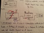
tried with diferent gains and the problem remains the same. i wonder if i am making a big stupid mistake here, but I've been the last 4 days testing every possibility I can think of with no result. the dual supply i'm using are 2 9v batteires. Below i leave you the schematics (the variable resistor sets a 3V offset, but adding that makes no effect, except that when connecting the 9V battery to the inputs, it reads -3.2V instead of -7.2V, without adding the battery though, it stays at -7,6V) and the breadboard altough its not very clear how all is connected.


if you need any more info and have any idea it would really be appreciated.
Thank you very much
I've been working on a EKG amplifier using the AD624. You have the pin connection and schematics for a gain = 1000, extracted from the datasheet below.

The big problem is, I connect everthing right, and the V output, when the two inputs are connected together (in theory, Vdif=0) keeps pointiong as -7,6V respect to ground. Not only that, but if I diosconnect the inputs it has little to no effect. It's as if it was saturated to -7,6V regardless of the inputs (i checked and the negative feedback loop from pin 9 to 10 is correct). the only change I can induce is a 0.5V change by connecting a 9V battery between the inputs.
tried with diferent gains and the problem remains the same. i wonder if i am making a big stupid mistake here, but I've been the last 4 days testing every possibility I can think of with no result. the dual supply i'm using are 2 9v batteires. Below i leave you the schematics (the variable resistor sets a 3V offset, but adding that makes no effect, except that when connecting the 9V battery to the inputs, it reads -3.2V instead of -7.2V, without adding the battery though, it stays at -7,6V) and the breadboard altough its not very clear how all is connected.


if you need any more info and have any idea it would really be appreciated.
Thank you very much
Last edited by a moderator:


